Elevator installation

a technology for installing elevators and cables, which is applied in the direction of elevators, transportation and packaging, building lifts, etc., can solve the problems that the different extension behavior of the cable strand cannot be completely compensated, and cannot be ruled ou

Inactive Publication Date: 2008-03-13
THYSSENKRUPP ELEVATOR AG (DE)
View PDF10 Cites 7 Cited by
  • Summary
  • Abstract
  • Description
  • Claims
  • Application Information

AI Technical Summary

Benefits of technology

[0038] To be able to detect a very great change in length of one of the two cable strands, it is advantageous if a control signal can be output by the sensor when a predetermined pivoting angle of the rocker or a predetermined distance between the lever arm and the car is exceeded. The control signal may be presented to an elevator control system of the elevator installation, so that, if the control signal is received, the elevator control system can output an optical or acoustic warning signal in order to indicate to the user that the two cable strands have very different cable lengths, for example because the cable strands have been in use for a relatively long time.
[0039] In the case of a particularly preferred embodiment of the invention, the two connecting links are respectively configured as pivotably mounted a

Problems solved by technology

Different extension behavior of the cable strands cannot be ruled out even if the car is subjected to uniform loading, since the cable strands are generally exposed to different frictional conditions.
However, the different extension behavior of the cab

Method used


Image

  • Elevator installation
  • Elevator installation
  • Elevator installation

Examples


second embodiment

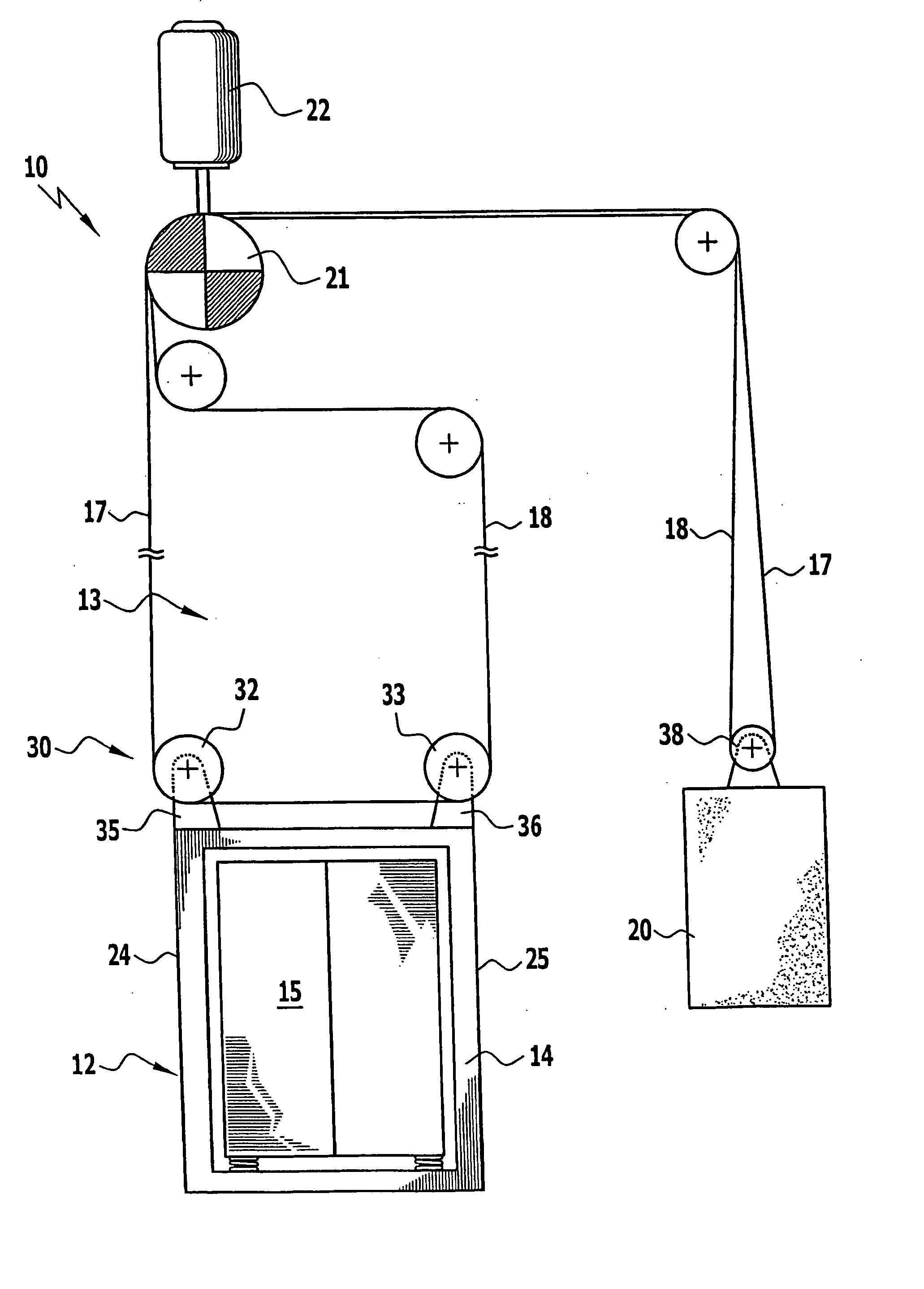
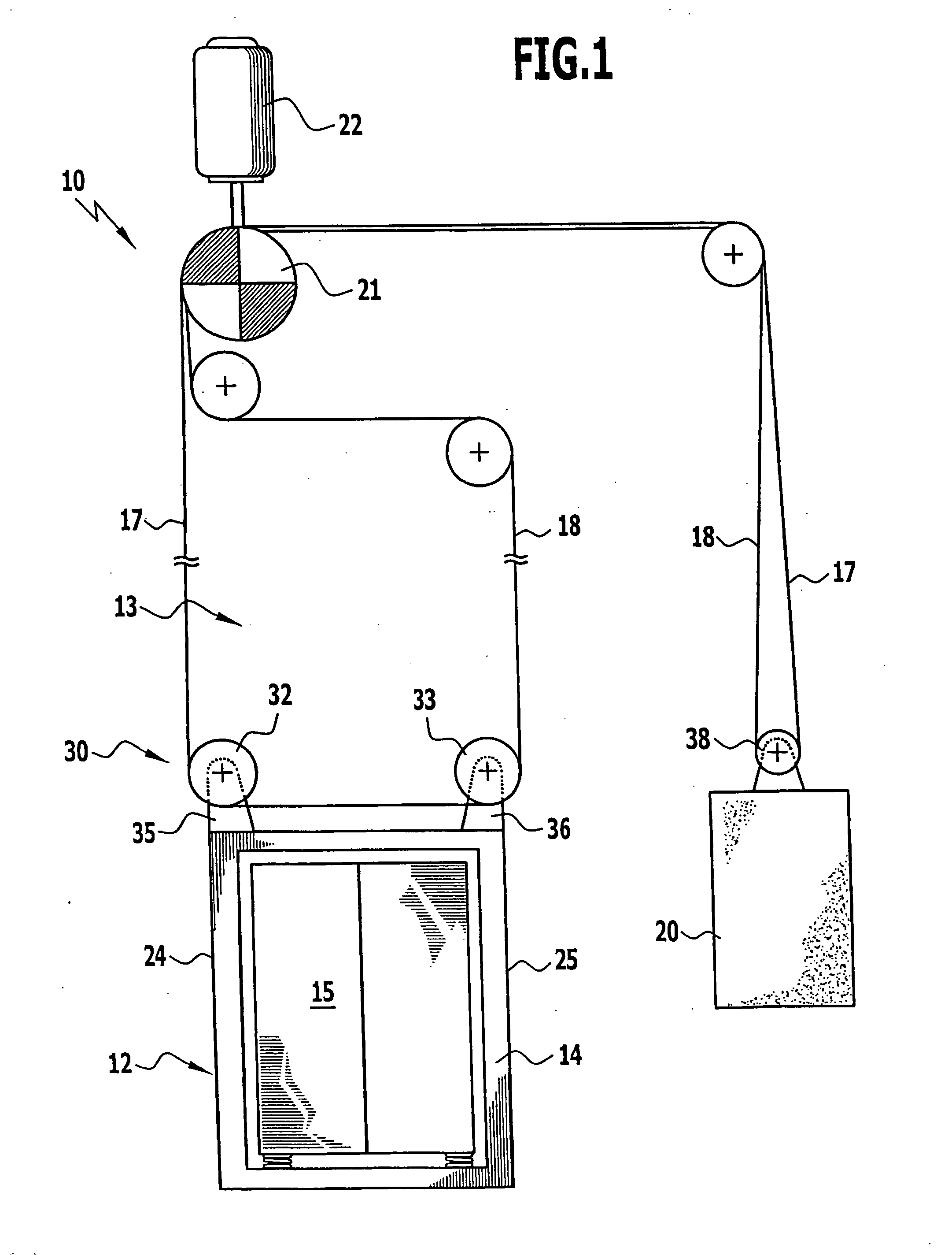
[0051] In FIG. 2, an elevator installation according to the invention is represented and provided overall with the reference numeral 40. In the same way as the embodiments that are represented in FIGS. 3 to 9 and described in detail below, this elevator installation is configured largely identically to the elevator installation 10. Therefore, the same reference numerals as in FIG. 1 are used for identical components in FIGS. 2 to 9. To avoid repetition, reference is made in this respect to the explanations given above.

[0052] The elevator installation 40 represented in FIG. 2 differs from the elevator installation 10 in that a cable length equalizing device 42 is disposed underneath the car cabin 15. This device comprises deflecting rollers 44 and 45, which are respectively mounted in a freely rotatable manner on a common carrier 47, which is held on the car cabin 15 by means of spring elements 49, 50. A car frame, as used in the case of the elevator installation 10 represented in FI...

third embodiment

[0055] In FIG. 3, an elevator installation is represented in the form of a cutout detail and provided overall with the reference numeral 60. In the case of this elevator installation, cable strands 61 and 62 are used, each having a number of individual cables 63 and 64, respectively. In a way corresponding to the embodiment represented in FIG. 2, the cable strands 61 and 62 are led around deflecting rollers of a cable length equalizing device 67 that are mounted on the underside of the car 12, but each individual cable 63 and 64 has a separate associated deflecting sheave 65 and 66, respectively, of the deflecting rollers. The individual deflecting sheaves 65 and 66 are rotatably held in relation to each other on the carrier 47, so that a length equalization can take place in each case between two individual cables 63 and 64 of the two cable strands 61 and 62, respectively, without the other individual cables 63 and 64 being influenced by it. It may also be provided here that each d...

fourth embodiment

[0056] In FIG. 4, an elevator installation according to the invention, with a cable length equalizing unit 74, is represented and provided overall with the reference numeral 70, in which installation deflecting rollers 71 and 72 disposed on the underside of the car 12 are held on a cable length equalizing element in the form of a hydraulic piston-cylinder assembly 73, which is fixed to the underside of the car 12. The piston-cylinder assembly 73 forms a linear adjusting system, with the aid of which the deflecting rollers 71, 72 can be displaced in opposite directions in relation to each other, in order to change the distance between the deflecting rollers 71 and 72. By changing this distance, changes of the cable lengths of the cable strands 61, 62 can be specifically equalized. In the case of this embodiment, too, the deflecting rollers 71, 72 may, as already shown in FIG. 3, comprise individual deflecting sheaves which can rotate in opposite directions and around each of which an...


PUM


Abstract

The invention relates to an elevator installation with at least one car, which can be made to travel in a shaft and is connected to a counterweight by means of two cable strands, which are associated with different sides of the car, and with a traction sheave, which can be driven by a motor and over which the two cable strands are led, the car being kept in a suspension ratio of 1:1. In order to develop the elevator installation in such a way that different extension behavior of the two cable strands can be equalized, it is proposed according to the invention that the two cable strands are coupled to each other by means of a cable length equalizing device disposed on the car and/or on the counterweight.

Description

[0001] This application is a continuation of international application number PCT / EP2005 / 011541 filed on Oct. 28, 2005. [0002] The present disclosure relates to the subject matter disclosed in international application number PCT / EP2005 / 011541 of Oct. 28, 2005 and European application number 05 005 443.6 of Mar. 12, 2005, which are incorporated herein by reference in their entirety and for all purposes.BACKGROUND OF THE INVENTION [0003] The invention relates to an elevator installation with at least one car, which can be made to travel in a shaft and is connected to a counterweight by means of two cable strands, which are associated with different sides of the car, and with a traction sheave, which can be driven by a motor and over which the two cable strands are led, the car being kept in a suspension ratio of 1:1. [0004] Elevator installations of this type are known from EP-A-1 329 412. In the case of this elevator installation, two cars which can be made to travel up and down ind...

Claims


Application Information

Patent Timeline
IPC IPC(8): B66B7/10
CPCB66B7/08B66B7/06B66B11/00
Inventor REUTER, GUENTER
Owner THYSSENKRUPP ELEVATOR AG (DE)
Why Eureka
Try Eureka