
Filter System for Ponds and Larger Aquariums

a filter system and aquarium technology, applied in the direction of filtration separation, water cleaning, separation processes, etc., can solve the problems of reducing the efficiency of the filter system, affecting the quality of the water, so as to achieve the effect of easy customization of secondary aspects

Inactive Publication Date: 2008-03-13
TOM DARREN CHRISTOPHER
View PDF23 Cites 34 Cited by
  • Summary
  • Abstract
  • Description
  • Claims
  • Application Information

AI Technical Summary

Benefits of technology

[0012]In many embodiments, the area immediately above the filter compartment may serve a secondary functional or aesthetic purpose. In some embodiments the top of the compartment may be a flat surface on which decorative or functional objects may be placed. In other embodiments the area above the compartment may be formed into elements for camouflaging the filter system. The elements may represent an animal, plant, rock formation, landmark, natural phenomenon, landscape, vehicle, building, icon, logo, human, artistic sculpture, piece of art, or any combination of these. In some embodiments, the water output from the pump may be part of the camouflaging element in the form of a waterfall, fountain or other complementary water feature. In other embodiments, the functional part of the filter compartment shares a common fastening mechanism with many different camouflaging elements, thereby enabling easy customization of the secondary aspects of the filter system.

Problems solved by technology

In many filter systems however; premature filter media clogging significantly reduces the filtering system's efficiency, leaving the water cloudy even with frequent media cleaning intervals.
Upward and side facing water intakes may be susceptible to algae growth on the water intake.
This algae growth may easily spread to the filter media immediately behind the intake grill, reducing filter capacity even while the water isn't flowing through the filter.
Another problem is that large particles (aquatic soil and other debris) stirred up by moving water and marine life may settle on upward facing water intakes or may float into side facing intakes clogging the filter system and reducing efficiency.
Current designs do not allow the use of the space immediately above or beside the intake since this would impede the flow of water into the filter.
The exposed intake area may also be an unattractive part of the visual landscape.

Method used


Image

  • Filter System for Ponds and Larger Aquariums
  • Filter System for Ponds and Larger Aquariums
  • Filter System for Ponds and Larger Aquariums

Examples


Embodiment Construction

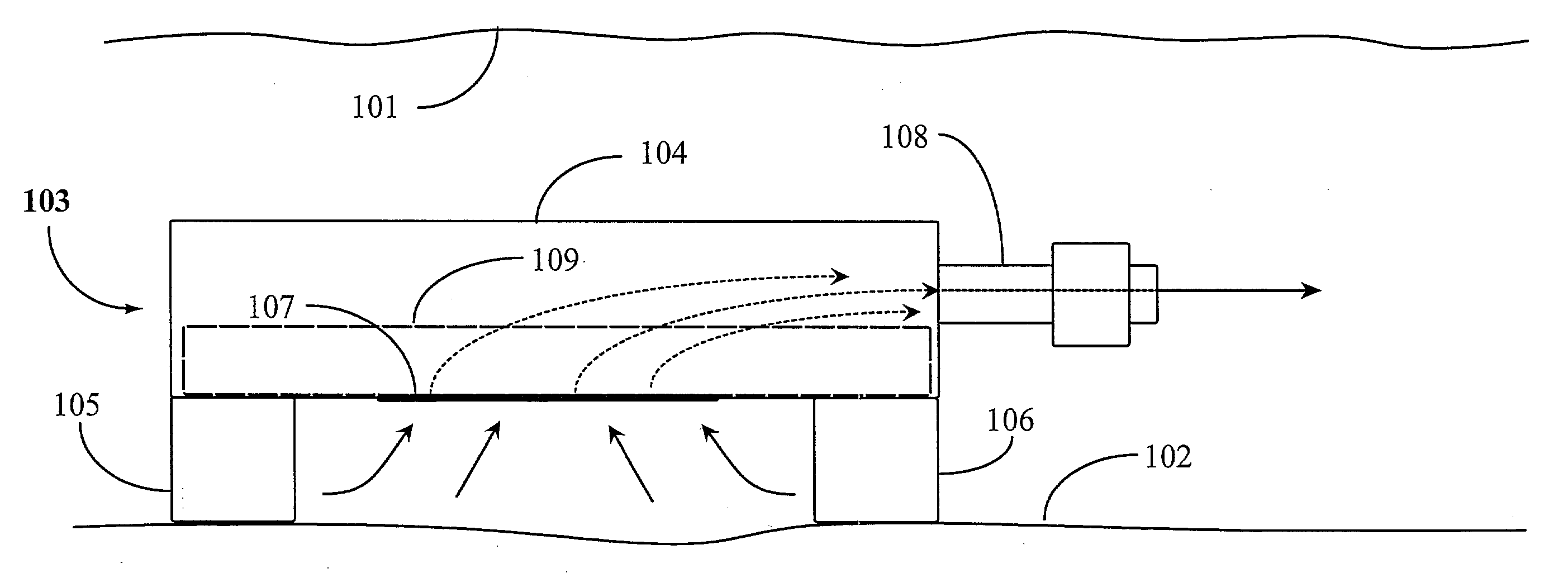
[0031]The inventor provides an improved filtering system for ponds and aquariums. The filtering system is described in enabling detail according to various embodiments described below in accordance with the illustrations. In all figures, solid arrows represent water flowing into and out of the embodiment and dotted arrows represent water flow within the embodiment.

[0032]FIG. 1 is a side view of a filter system 103 according to an embodiment of the present invention. Filter system 103, also referred to herein as filter 103, is illustrated in a submerged position in a pond. Filter 103 rests, in this example, on a pond floor 102. Filter 103 is submerged completely in the pond as illustrated by a top water line 101.

[0033]Filter 103 includes a filter compartment 104. Compartment 104 is adapted to contain filter media 109 such as charcoal, plastic mesh media, or other suitable water-filtering media. Filter compartment 104 is generally a hollow enclosure having four sides and a top and bot...


PUM

PropertyMeasurementUnit
Forceaaaaaaaaaa
Shapeaaaaaaaaaa
Distanceaaaaaaaaaa

Abstract

A filter system includes a filter compartment enclosing a filtering media, a downward-facing intake into the filter compartment, the intake submerged below the surface of the fluid and elevated above the floor of the fluid container, and an outlet in the filter compartment for connection to a suction source, so that fluid is drawn upward into the downward-facing intake and through the filtering media.

Description

CROSS-REFERENCE TO RELATED APPLICATIONS[0001]This application claims priority to U.S. provisional patent application Ser. No. 60 / 842,886, entitled “Submerged Pond Filter with Algae and Large Particle Debris Exclusion” filed on Sep. 07, 2006, and U.S. provisional patent application Ser. No. 60 / 850,201, entitled “Submerged Pond Filter with Multi-Purpose Footprint” filed on Oct. 06, 2006, both of which are incorporated herein at least by reference.BACKGROUND OF THE INVENTION[0002]1. Field of the Invention[0003]The present invention is in the field of filtering equipment for ponds and large aquariums and pertains particularly to a filtering system that resists algae and clogging with particulate matter.[0004]2. Discussion of the State of the Art[0005]Maintaining clear water in aquariums and ponds is one of the most important priorities. Clear oxygenated water promotes the health of fish and other wildlife that may inhabit a pond or aquarium and helps to maintain aesthetic appeal. Effici...

Claims


Application Information

Patent Timeline
IPC IPC(8): B01D29/00
CPCA01K63/045
Inventor TOM, DARREN CHRISTOPHER
Owner TOM DARREN CHRISTOPHER
Learn More