
Switch control system of HomePlug and method thereof

a control system and switch technology, applied in the field of power line home network, can solve the problems of cost and space saving, and achieve the effects of preventing control error, saving cost and space, and improving convenience of us

Inactive Publication Date: 2008-03-13
ARCADYAN
View PDF2 Cites 2 Cited by
  • Summary
  • Abstract
  • Description
  • Claims
  • Application Information

AI Technical Summary

Benefits of technology

[0006]It is therefore a primary object of the present invention to provide a switch control system of HomePlug and method thereof that prevent interference from other controllers by a server ID saved in a switch.
[0008]It is a further object of the present invention to provide a switch control system of HomePlug and method thereof that connect switches of appliances by HomePlug specification. Without dedicated network cables for connectivity, both cost and space are saved.
[0009]It is a further object of the present invention to provide a switch control system of HomePlug and method thereof that control different switches by the central server. There is no need to use a lot of controllers for each of the switches. Thus the convenience of use is improved.
[0010]In order to achieve objects and advantages, the present invention uses at least one switch and a central server, both having network function. The network device must have a physical location that is also referred to as the MAC address, plus a server ID of the central server to from a switch identification number. Through the switch identification number, the central server learns status of the switch and further switches the status so as to prevent control error. The switches identifies whether the server is a set controller by the written-in server ID so as to avoid interference from other controllers. Furthermore, the structure of the present invention is base on HomePlug specification so that dedicated network cables are saved and the cost is down. The beauty of interior design is also not affected. In addition, only one central server can control each of the switches. Thus the convenience of use is enhanced.

Problems solved by technology

Without dedicated network cables for connectivity, both cost and space are saved.

Method used


Image

  • Switch control system of HomePlug and method thereof
  • Switch control system of HomePlug and method thereof
  • Switch control system of HomePlug and method thereof

Examples


Embodiment Construction

[0017]Without server IDs, controllers can't be identified correctly by conventional local area network control system and easy to be interfered with by other controllers. Moreover, each switch can't be effectively managed by the server. Furthermore, conventional local area network control system uses a lot of network cables for connection. This not only needs a lot of space for distribution but also increase cost. Therefore, the present invention provides a switch control system and method thereof base on HomePlug technology for improving above shortcomings.

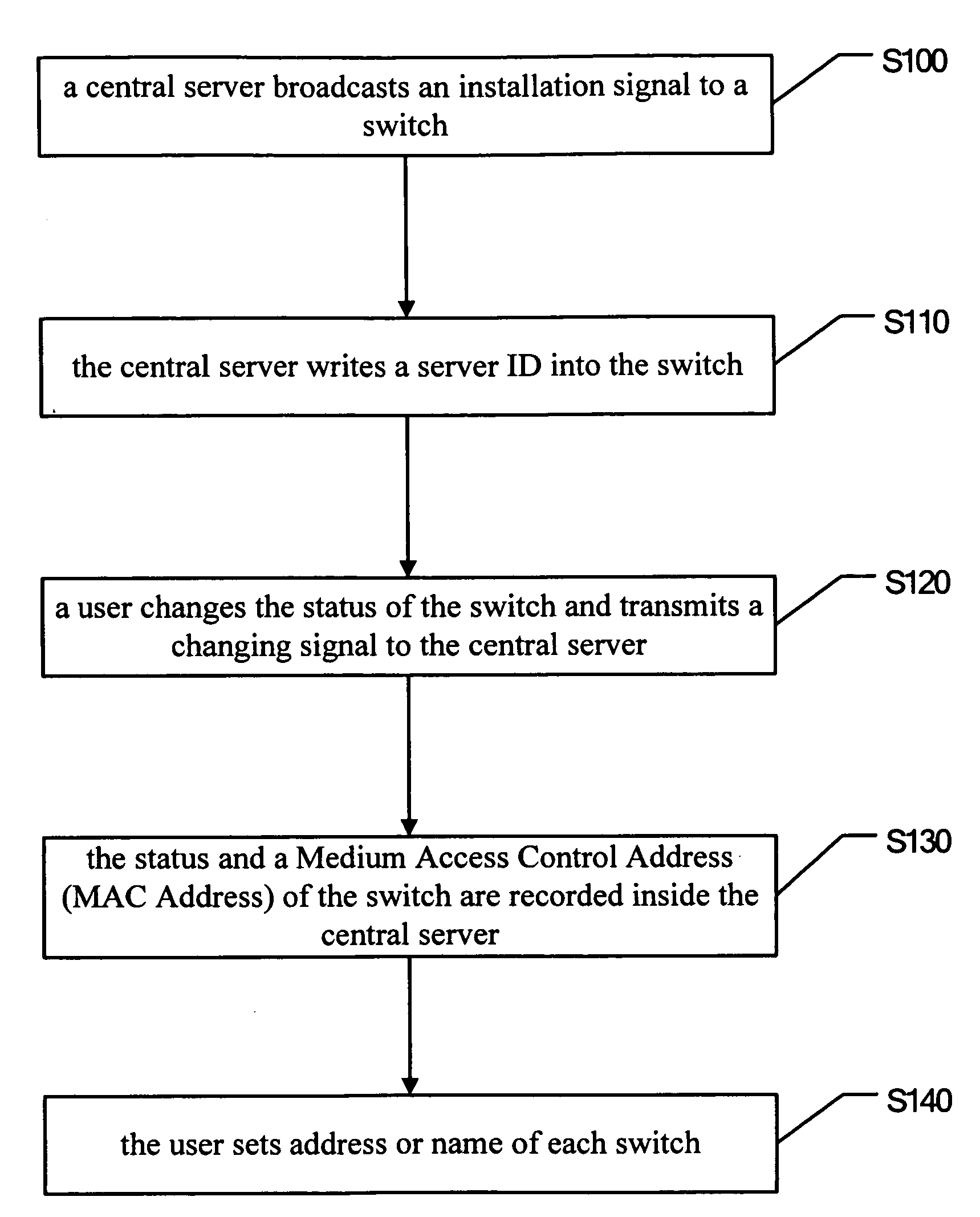
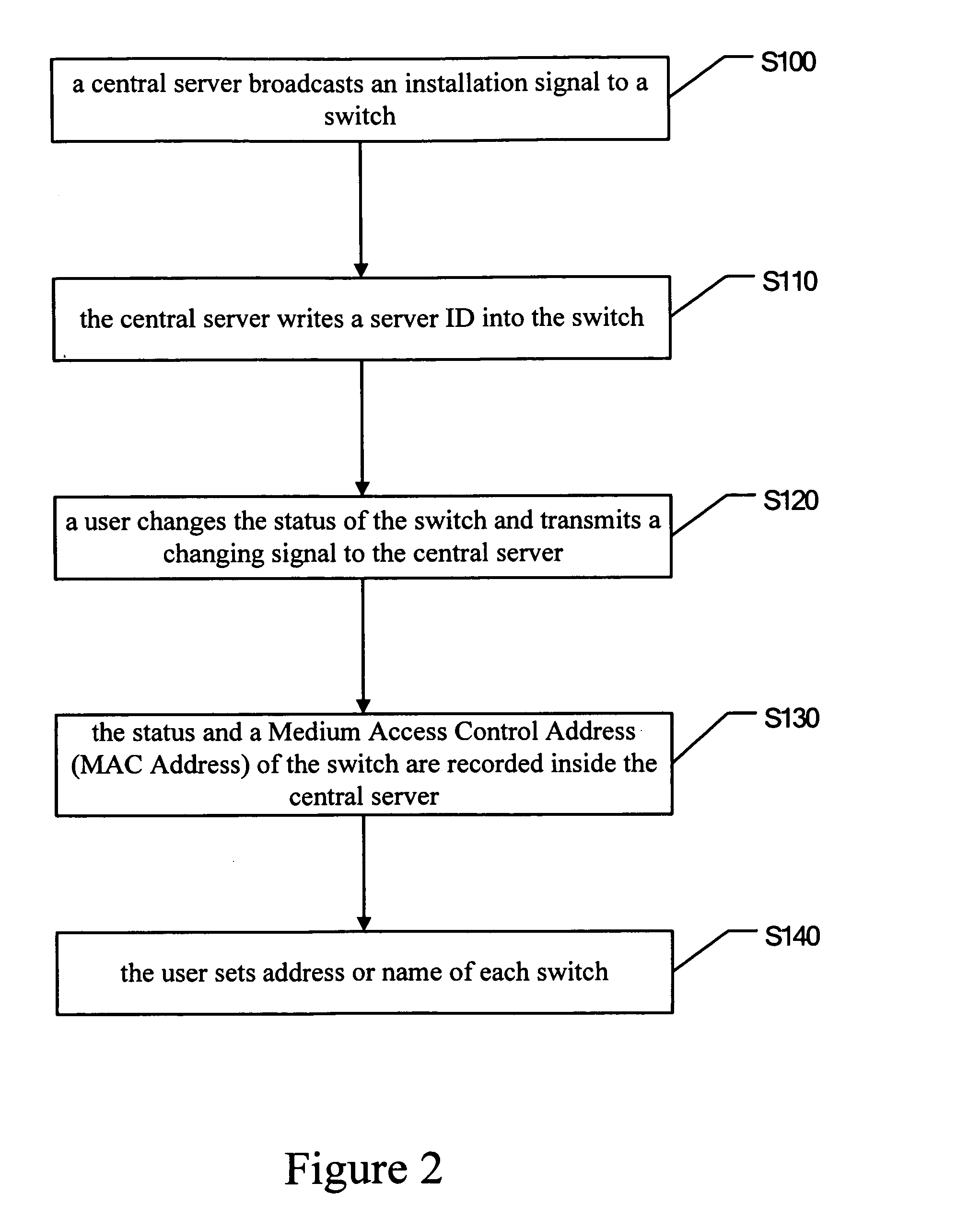
[0018]Refer to FIG. 2, firstly, take the step S100—a central server broadcasts an installation signal to a switch. For control of the switch, the switch needs to be set in advance. The central server sends an installation signal to a switch located on the same circuitry. Then run the step S110, the central server writes a server ID into the switch. While sending the installation signal to a switch, the server writes the server ID...


PUM


Abstract

A switch control system of HomePlug and method thereof are disclosed. At least a switch and a central server are connected to form a home network. By a switch identification number composed of a Medium Access Control Address (MAC address) of the switch and a server identification (ID), the central server identifies the status of each switch. By a power line, the central server connects with the switch for data transmission and switching the status of the switch. By the server ID, the switch is not affected by interference from other controller.

Description

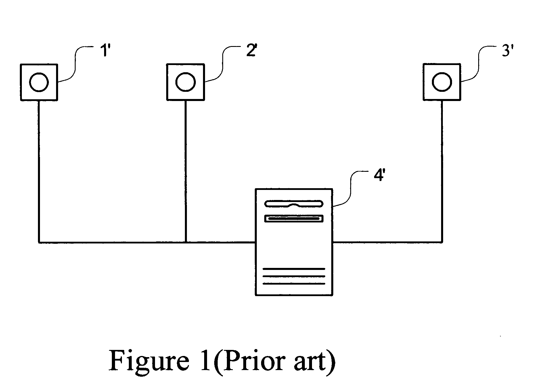
BACKGROUND OF THE INVENTION[0001]The present invention relates to a power line home network, especially to a switch control system of HomePlug and method thereof.[0002]Nowadays information and electronics industries have been highly developed, especially the home network in recent years. Miscellaneous high-tech appliances have been used by each family. Thus there are more and more switches for control of those electronics. It is an important issue to control these switches effectively and conveniently.[0003]Refer to FIG. 1, it shows a schematic drawing of a control system for a local area network. A first switch 1′, a second switch 2′, and a third switch 3′, all having network function, are connected with a central server 4′ for control above switches to form a local area network. A Medium Access Control Layer (MAC Layer) of the switch is used for packets delivery inside the local area network.[0004]However, once a controller is disposed inside the local area network, if the switch ...

Claims


Application Information

Patent Timeline
IPC IPC(8): H05B37/02
CPCH04B3/542H04B2203/5408H04B2203/5445H04L67/12H04L29/12254H04L61/2038H04B2203/5454H04L61/5038
Inventor SYU, WEI-HAOTSAO, CHIN-FULIN, CHENG-RU
Owner ARCADYAN
Learn More