Apparatus and method for detecting vehicles by identifying light spots from captured images

a technology of light spots and apparatus, applied in road vehicle traffic control, instruments, computing, etc., can solve the problems of erroneous detection of vehicles, erroneous perception of light spots originating from street lamps or building neon signs, etc., and achieve accurate detection of vehicles and accurate discrimination

Active Publication Date: 2008-03-13
DENSO CORP
View PDF3 Cites 35 Cited by
  • Summary
  • Abstract
  • Description
  • Claims
  • Application Information

AI Technical Summary

Benefits of technology

[0008]The present invention has been made in light of the problem presented above and has as its object to enable accurate discrimination between a light spot originating from a vehicle and a light spot originating from an object other than a vehicle and to enable accurate detection of vehicles.
[0012]According to each of the vehicle detection apparatuses mentioned above, a distance to a light spot is calculated by the distance calculating means. Then, the light spot is determined as to whether it originates from a vehicle, based on a difference (pitching amount) between a vertical coordinate (first coordinate) of the light spot and a vertical coordinate (second coordinate) corresponding to the distance calculated by the distance calculating means. Thus, vehicles can be accurately detected.

Problems solved by technology

However, the vehicle detection apparatus disclosed in the above literature raises a problem that light spots originating from street lamps or building neon signs could be regarded erroneously as being light spots originating from a preceding actual vehicle, when those lamps / signs are positioned in the captured images as if they are light spots from actual preceding vehicles.
This results in erroneous detection of vehicles, if such a particular positional relationship between the street lamps or building neon signs and actual preceding vehicles happens in capturing forward images.

Method used


Image

  • Apparatus and method for detecting vehicles by identifying light spots from captured images
  • Apparatus and method for detecting vehicles by identifying light spots from captured images
  • Apparatus and method for detecting vehicles by identifying light spots from captured images

Examples


first embodiment

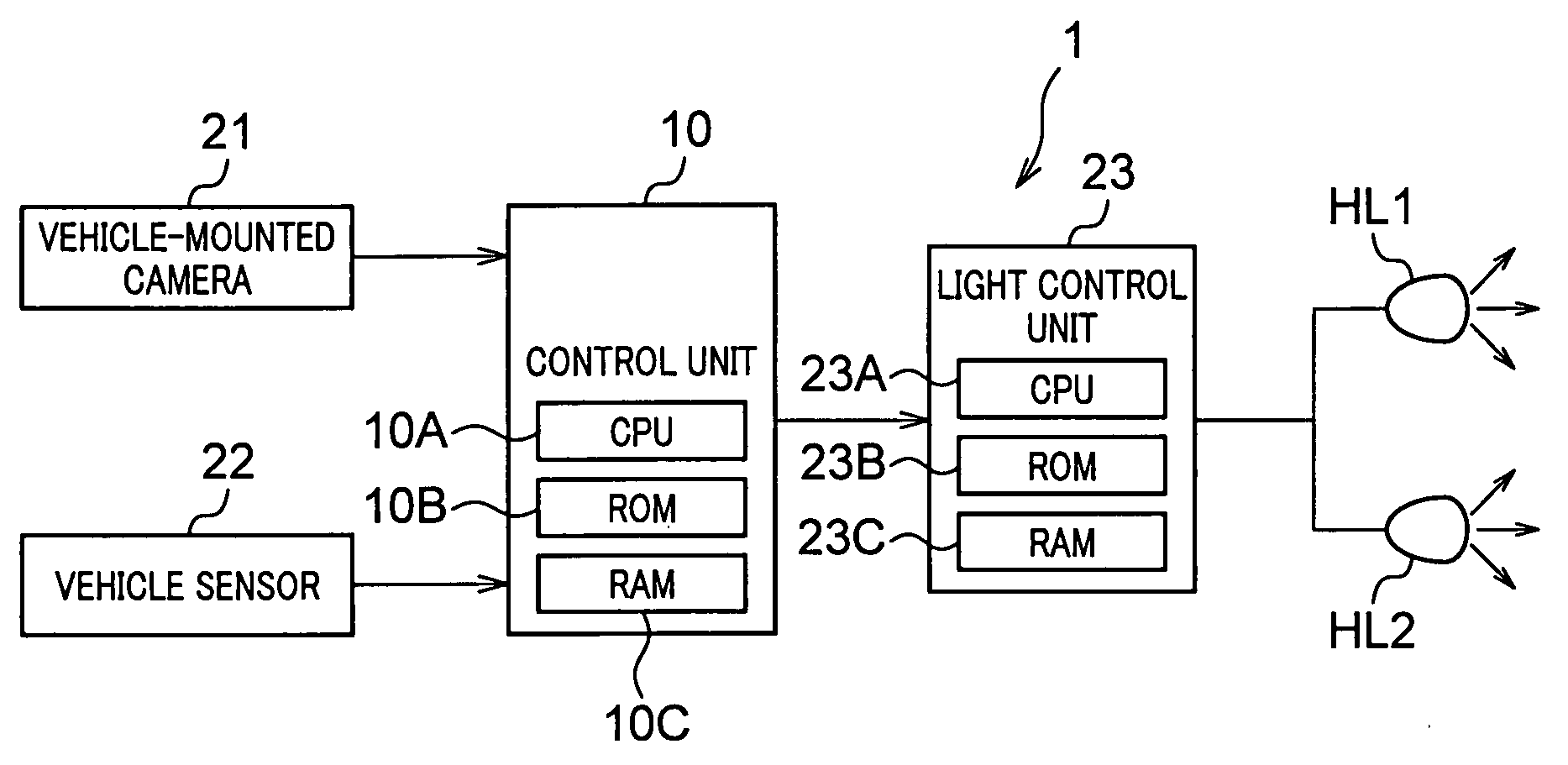
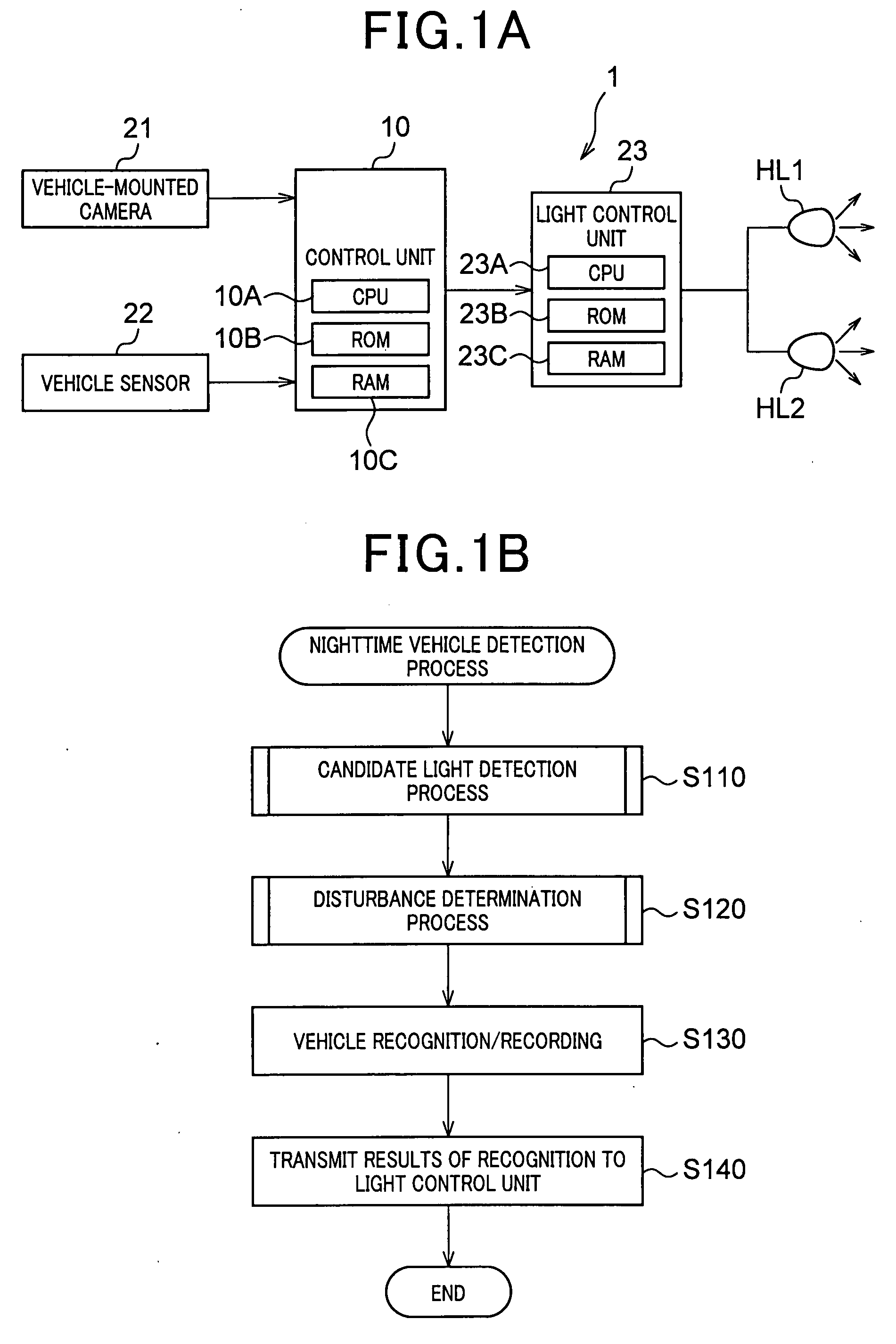
[0026]FIG. 1A is a schematic block diagram illustrating a light control apparatus 1 to which a vehicle detection apparatus of the present invention is applied.

[0027]The light control apparatus 1 is loaded on a vehicle, such as a passenger car. The light control apparatus 1 detects vehicles traveling ahead in the same direction and vehicles coming from the opposite direction, and carries out processes for switching the headlamps between low and high beams according to the results of the detection.

[0028]In particular, as shown in FIG. 1A, the light control apparatus 1 includes a control unit 10, a vehicle-mounted camera 21, a vehicle sensor 22 and a light control unit 23.

[0029]The vehicle-mounted camera 21 is located at the front of the vehicle to capture images in a forward direction during the hours of darkness (e.g., when the surrounding is so dark as to need use of headlamps, such as at night, in a mist and in the middle of a tunnel) and to transmit captured images to the control ...

second embodiment

[0072]Hereinafter is described a light control apparatus 2 according to a second embodiment of the present invention. In the second embodiment, a detailed description will be provided only for the components which are different from those of the light control apparatus 1 in the first embodiment. Also, in the present embodiment, the identical or similar components to those in the first embodiment are given the same reference numerals for the sake of omitting explanation.

[0073]In the light control apparatus 2, the nighttime vehicle detection process is partly different from that of the light control apparatus 1 in the first embodiment.

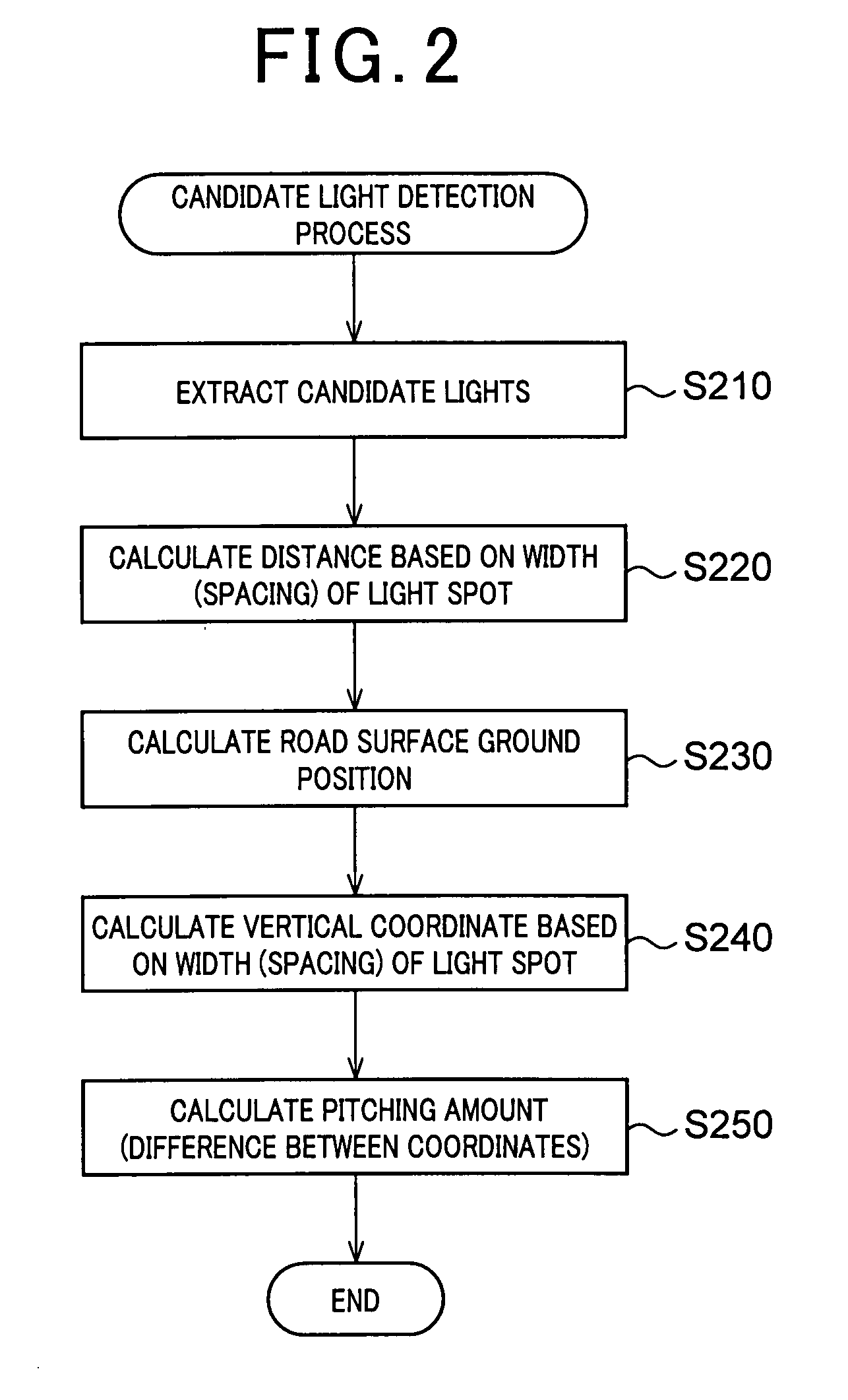
[0074]For example, a procedure as shown in FIG. 6B is carried out in the candidate light detection process. Specifically, the same steps as shown in FIG. 2 are taken up to step S230. After finishing the processing at step S230, a distance to a light spot is calculated based on a vertical coordinate of the road surface ground position (step S710 associate...


PUM


Abstract

A vehicle detection apparatus detects vehicles traveling on a road with their lights turned on. The apparatus captures images of a road, detects a light spot from captured images, and detects a first vertical coordinate of the light spot in the images. The apparatus further calculates a distance to the light spot based on a horizontal length of the light spot in the images and detects a second vertical coordinate corresponding to the calculated distance, based on correlated data in which vertical coordinates and distances in an image are correlated in advance. The apparatus further calculates a pitching amount that indicates a difference between the first and second coordinates and determines whether or not the light spot originates from a vehicle, based on the pitching amount.

Description

CROSS-REFERENCE TO RELATED APPLICATION[0001]This application is based on and claims the benefit of priority from earlier Japanese Patent Application No. 2006-243175 filed Sep. 7, 2006, the description of which is incorporated herein by reference.BACKGROUND OF THE INVENTION[0002]1. Field of the Invention[0003]The present invention relates to a vehicle detection apparatus for detecting vehicles traveling with their light turned on and to a light control apparatus utilizing the vehicle detection apparatus.[0004]2. Description of the Related Art[0005]Vehicle detection apparatuses have been known, which can detect vehicles traveling with their light turned on during the hours of darkness. This type of apparatuses include, for example, one which employs a technique for detecting headlamps or tail lamps of vehicles by processing images captured by a camera.[0006]In processing a captured image, such a vehicle detection apparatus entails the necessity of preventing confusion between light sp...

Claims


Application Information

Patent Timeline
Patent Type & Authority Applications(United States)
IPC IPC(8): G08G1/017
CPCG06K9/00798G08G1/16G06K9/3241G06K9/00825G08G1/167G06V20/584G06V20/588G06V10/255
Inventor KOBAYASHI, KENJIKUMON, HIROAKI
Owner DENSO CORP
Why Eureka
Try Eureka