Polarization switching/variable directivity antenna

a variable directivity, polarization switching technology, applied in the direction of polarised antenna unit combinations, substantially flat resonant elements, resonant antennas, etc., can solve the problems of generating a completely circularly polarized, elliptically polarized wave, deteriorating communication quality, etc., to achieve efficient switching of the maximum gain direction, good axial ratio characteristics, and better circular polarized wave characteristics

Inactive Publication Date: 2008-03-13
PANASONIC CORP
View PDF3 Cites 15 Cited by
  • Summary
  • Abstract
  • Description
  • Claims
  • Application Information

AI Technical Summary

Benefits of technology

[0025] Further preferably, the circular polarization index is no less than 1.1 and no more than 1.3. Under this condition, further better circularly polarized wave characteristics can be obtained.
[0026] Each second slot 20b,20c comprised by the at least two polarization switching elements may also be a first slot 20a comprised by the at least one directivity switching element, such that both of the at least one polarization switching switch 18 and the at least two directivity switching switches 17 are provided on the second slot 20b,20c, whereby each polarization switching element 16 serves both a polarization switching function and a directivity switching function. With this construction, an element which doubles as a directivity switching element and a polarization switching element can be realized, thus enabling a more efficient switching of the maximum gain direction into multiple directions.
[0027] A polarization switching / variable directivity antenna of the present invention simultaneously realizes, in a simple construction which uses no phase shifters, and in a construction which employs a single feed line and in which an insertion loss of any switching element that might otherwise be necessary for switching a plurality of feed lines is avoided, switching of a maximum gain direction of radiation directivity and switching of the rotation direction of a circularly polarized wave which has good axial ratio characteristics along the maximum gain direction.

Problems solved by technology

This multipath propagation is a cause for deterioration of the communication quality.
Usually, it is difficult to generate a completely circularly polarized wave, because it will merge with a polarization component of the opposite rotation, thus resulting in an elliptically polarized wave.
However, as an antenna to be internalized in a laptop computer or an antenna for a mobile device, circular polarization antennas such as those shown in FIGS. 17B and 17C are unsuitable.
The position and orientation of such a mobile terminal may greatly change, so that a circular polarization antenna having a fixed rotation direction may not be able to perform transmission / reception when it is reversed in orientation, for example.
However, an antenna having the above-described conventional construction is unsuitable as an antenna for a small-sized device or terminal because of problems such as: a plurality of phase shifters being required, thus resulting in complicated construction and control, and switching of a plurality of feed lines being required, thus resulting in a large insertion loss associated with switching elements.

Method used


Image

  • Polarization switching/variable directivity antenna
  • Polarization switching/variable directivity antenna
  • Polarization switching/variable directivity antenna

Examples


embodiment 1

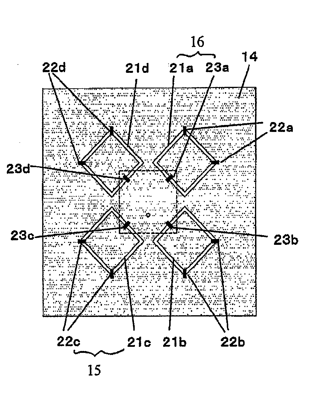
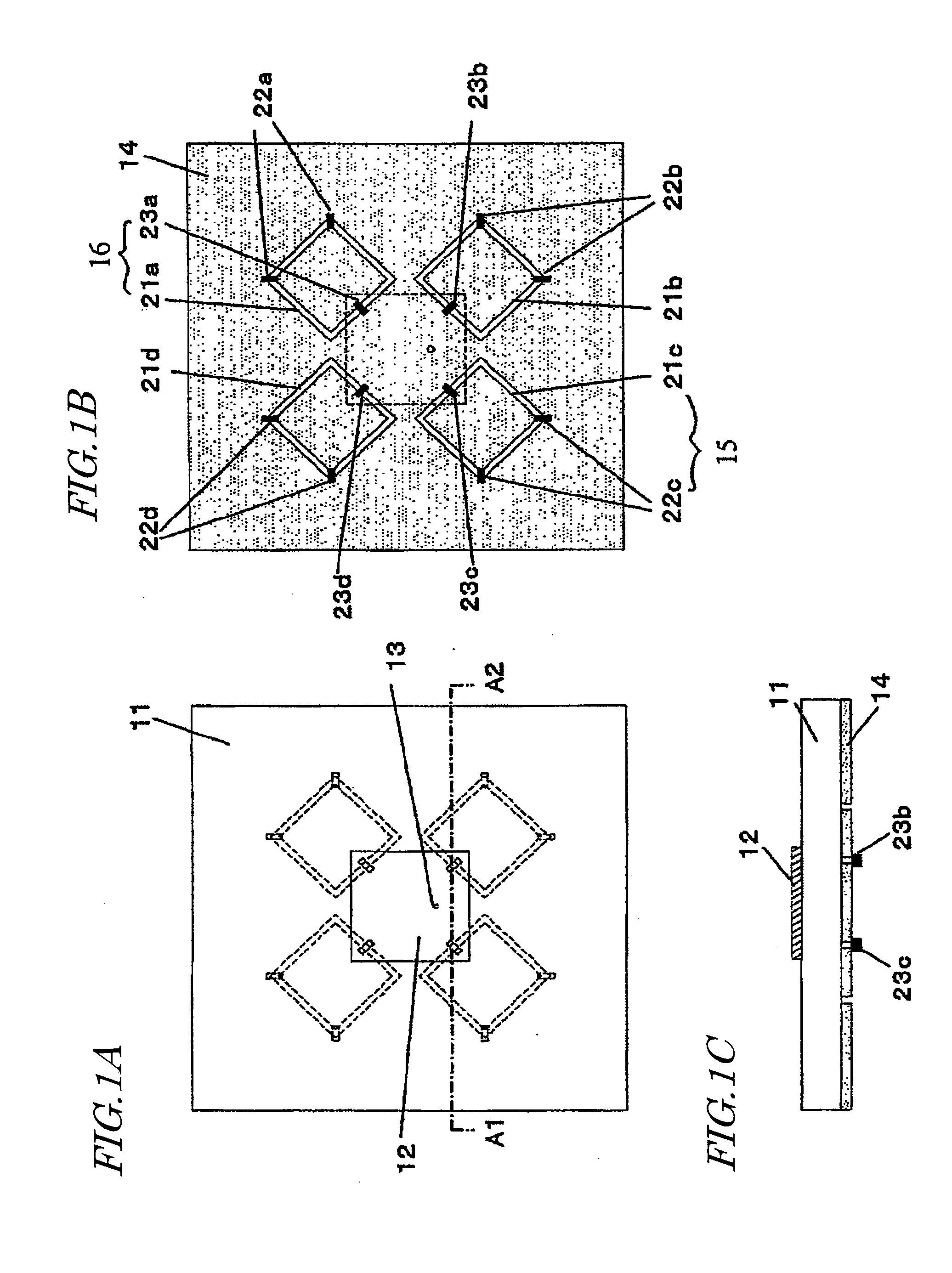
[0048] First, FIGS. 1A to 1C, which illustrate Embodiment 1 of the present invention, will be referred to. FIG. 1A is a see-through view of a first surface of a dielectric substrate 11. FIG. 1(b) is a see-through view of a second surface of the dielectric substrate 11 which opposes the first surface. FIG. 1(c) is a cross-sectional view taken along line A1-A2 in FIG. 1A.

[0049] According to Embodiment 1, each polarization switching element 16 serves both a polarization switching function and a directivity switching function. In other words, each polarization switching element 16 doubles also as a directivity switching element 15.

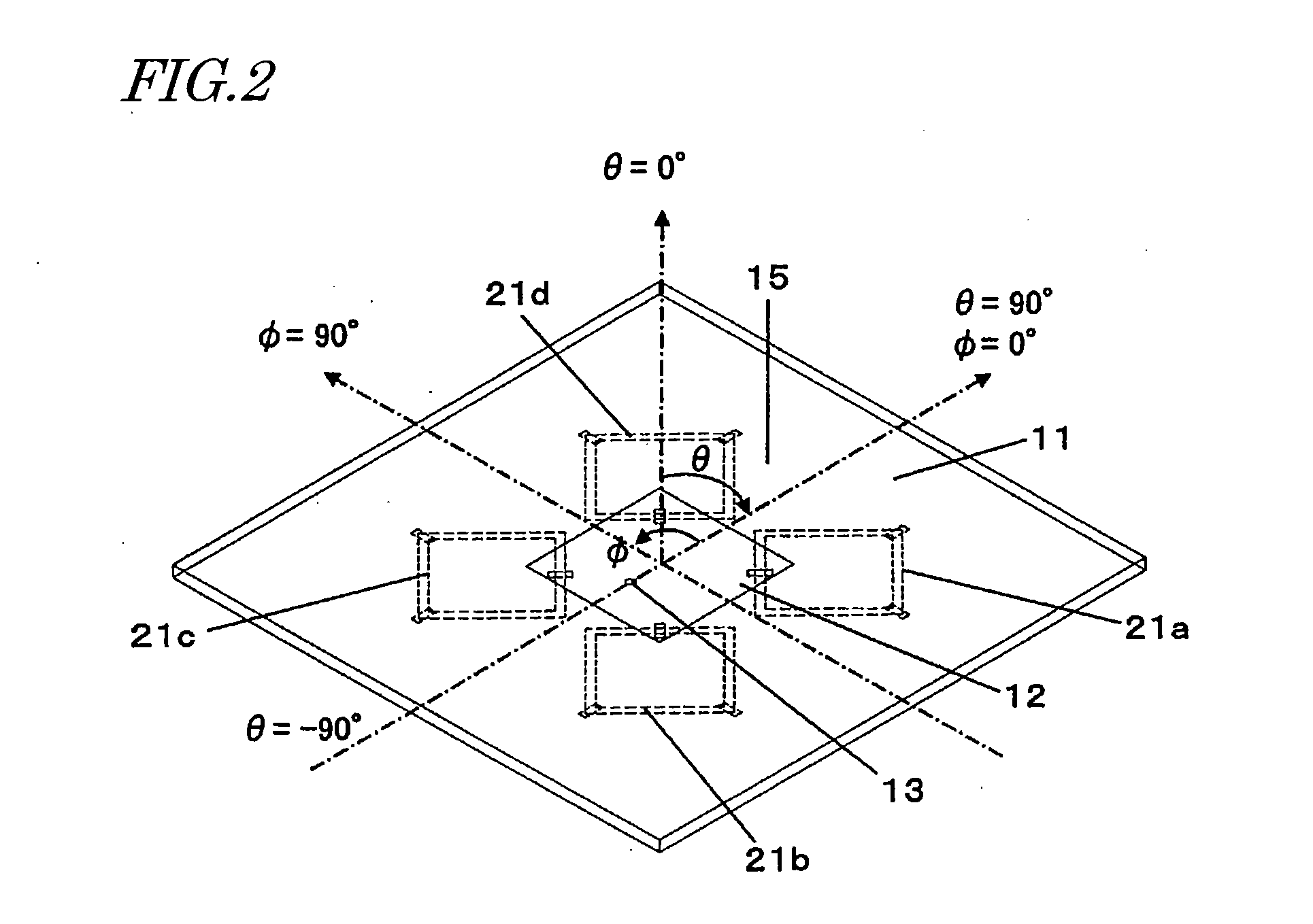
[0050] As shown in FIG. 1, the antenna of the present embodiment includes a radiation conductor plate 12 on the first surface of the dielectric substrate 11, and a ground conductor plate 14 on the opposing second surface. Slots 21a to 21d are provided in the ground conductor plate 14 on the second surface. Each of the slots 21a to 21d has at least two direct...

example 1

[0082] Hereinafter, Example 1 of the present invention will be described. The antenna of Example 1 has the construction shown in FIGS. 1A to 1C, and an enlarged view of the slot section is as shown in FIG. 3. The constituent elements of Example 1 are as shown in Table 2.

TABLE 2dielectricdielectric constant: 2.08substrate 11size: 13.5 × 13.5 × 0.4 mmradiationsquareconductor plate 12length L of one side: 3.7 mmslots 21a to 21dsquare looplength s1 of one side: 2.9 mmslot width w1: 0.2 mmoverlap Δslength d of one side: 1.10 mmarea of Δs: 0.605 mm2

[0083] Herein, the radiation conductor plate is sized so as to resonate in the TM mode at 25.4GHz. In this case, the Q0 of the radiation conductor plate 12 is calculated to be 22.8, with the circular polarization index being 1.00. In Example 1, the directivity switching elements are allowed to function as directors.

[0084]FIGS. 8A, 8B, 8C and 8D are diagrams showing examples of how the directivity switching switches 22a to 22d and the polariz...

embodiment 2

[0092] Next, with reference to the drawings, a polarization switching / variable directivity antenna according to Embodiment 2 of the present invention will be described. FIG. 13 is a see-through view of a first substrate surface according to Embodiment 2 of the present invention. Portions which are drawn by broken lines are meant to be formed on a second substrate surface. The detailed description of any portion that has an identical counterpart in Embodiment 1 will be omitted.

[0093] In Embodiment 1, each polarization switching element 16 has both of a polarization switching function and a directivity switching function. In Embodiment 2, however, polarization switching elements and a directivity switching element are independently provided.

[0094] In Embodiment 2, each polarization switching element 16 is composed of a loop-shaped slot 20b and polarization switching switches 18a and 18b. The conditions which must be satisfied by the polarization switching elements 16 are the same as...


PUM


Abstract

A polarization switching/variable directivity antenna according to the present invention includes a radiation conductor plate 12 on a front face, and a ground conductor plate 14 on a rear face, of a dielectric substrate 11. At least one directivity switching element and at least two polarization switching elements are provided within the ground conductor plate 14 on the rear face. The directivity switching element includes a first slot which is formed by a removing a loop-like portion from the ground conductor plate 14 and at least two directivity switching switches (22a to 22d). Each polarization switching element includes a first slot which is formed by removing a loop-like portion from the ground conductor plate 14 and at least one polarization switching switch (23a to 23d). Switching of a maximum gain direction of radiation directivity of the antenna is realized through control of the directivity switching switches 22a to 22d, and switching of the rotation direction of a circularly polarized wave which is emitted from the antenna is realized through control of the polarization switching switches 23a to 23d.

Description

[0001] This is a continuation of International Application No. PCT / JP2007 / 054517 with an international filing date of Mar. 8, 2007, which claims priority of Japanese Patent Application No. 2006-111756, filed on Apr. 14, 2006, the contents of which are hereby incorporated by reference.BACKGROUND OF THE INVENTION [0002] 1. Field of the Invention [0003] The present invention relates to an antenna which is suitable for high-quality wireless communications in the microwave and extremely high frequency ranges, where communications are performed while switching the rotation direction of a circularly polarized wave and a maximum gain direction of radiation directivity. [0004] 2. Description of the Related Art [0005] In recent years, there are increasing needs for rapid large-capacity communications in a closed space, e.g., an indoor space, as exemplified by indoor wireless LAN, for example. In a closed space such as an indoor space, there are not only direct waves along a line-of-sight betw...

Claims


Application Information

Patent Timeline
Patent Type & Authority Applications(United States)
IPC IPC(8): H01Q1/48
CPCH01Q3/44H01Q21/24H01Q9/0442H01Q9/0407
Inventor MATSUSHITA, AKIOFUJISHIMA, TOMOYASU
Owner PANASONIC CORP
Why Eureka
Try Eureka