Cleaning apparatus

a technology of cleaning equipment and batteries, applied in the direction of cleaning equipment, cell components, cell component details, etc., can solve the problem of having to have batteries availabl

Inactive Publication Date: 2008-03-13
ALFRED KARCHER GMBH & CO KG
View PDF11 Cites 25 Cited by
  • Summary
  • Abstract
  • Description
  • Claims
  • Application Information

AI Technical Summary

Benefits of technology

[0009] Removal of the mounting part from the battery chamber increases the space within the battery chamber, with the result that it is also possible to insert into the battery chamber extraneous batteries with a larger physical volume than batteries which are matched to the cleaning apparatus. The user therefore particularly has the possibility of using extraneous batteries, which are already available to him in connection with the supply of power to his electric tools, for example an electric drill or electric screwdriver, in order to also supply power to the cleaning apparatus.
[0011] In an advantageous embodiment, the insertion of the plug connector part into the plug connector receptacle is made easier by guide elements which interact with one another being disposed on the plug connector receptacle and on the plug connector part.
[0023] In an advantageous embodiment, the establishment of the mechanical connection between the battery and the mounting part is made easier by the at least one positively locking element being disposed on an end face of the mounting part, which end face faces the interior of the battery chamber when the mounting part is inserted into the battery chamber. In a configuration of this type, the positively locking element is easily accessible to the user, he can easily bring the battery into contact with the at least one positively locking element. For example, the positively locking element can form a guide rail which extends in the insertion direction of the battery and onto which the battery can be pushed during insertion into the battery chamber.
[0028] It is advantageous, particularly when the cleaning apparatus is configured as a suction apparatus, for the housing to comprise a housing lower part and a housing upper part which can be placed onto said housing lower part, the cleaning unit and the battery chamber being disposed in the housing upper part. An arrangement of this type has the advantage that no electrical connections between the plug connector part and the cleaning unit driven by an electric motor have to be disconnected when the housing lower part and the housing upper part are separated.
[0029] With regard to a physical shape of the cleaning apparatus which is as compact as possible, it is advantageous when the battery chamber is disposed laterally next to the cleaning unit. When the cleaning apparatus is configured as a suction unit, it is advantageous when the battery chamber extends as far as a point where it is beneath the upper edge of the dirt-collection container.

Problems solved by technology

However, this is associated with the disadvantage that the respectively matched batteries have to be available to the user and other batteries, which the user already uses for electric tools for example, cannot be used.

Method used


Image

  • Cleaning apparatus
  • Cleaning apparatus
  • Cleaning apparatus

Examples


Embodiment Construction

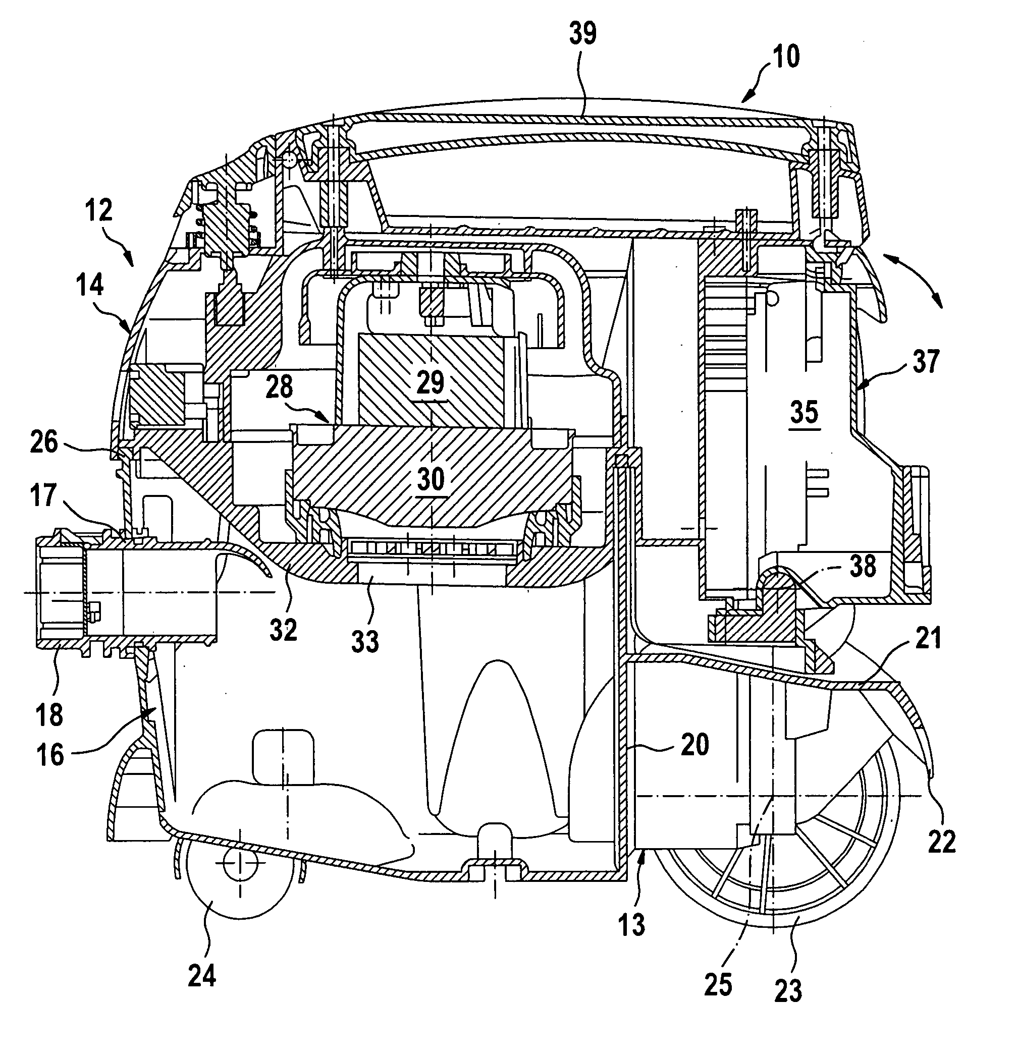
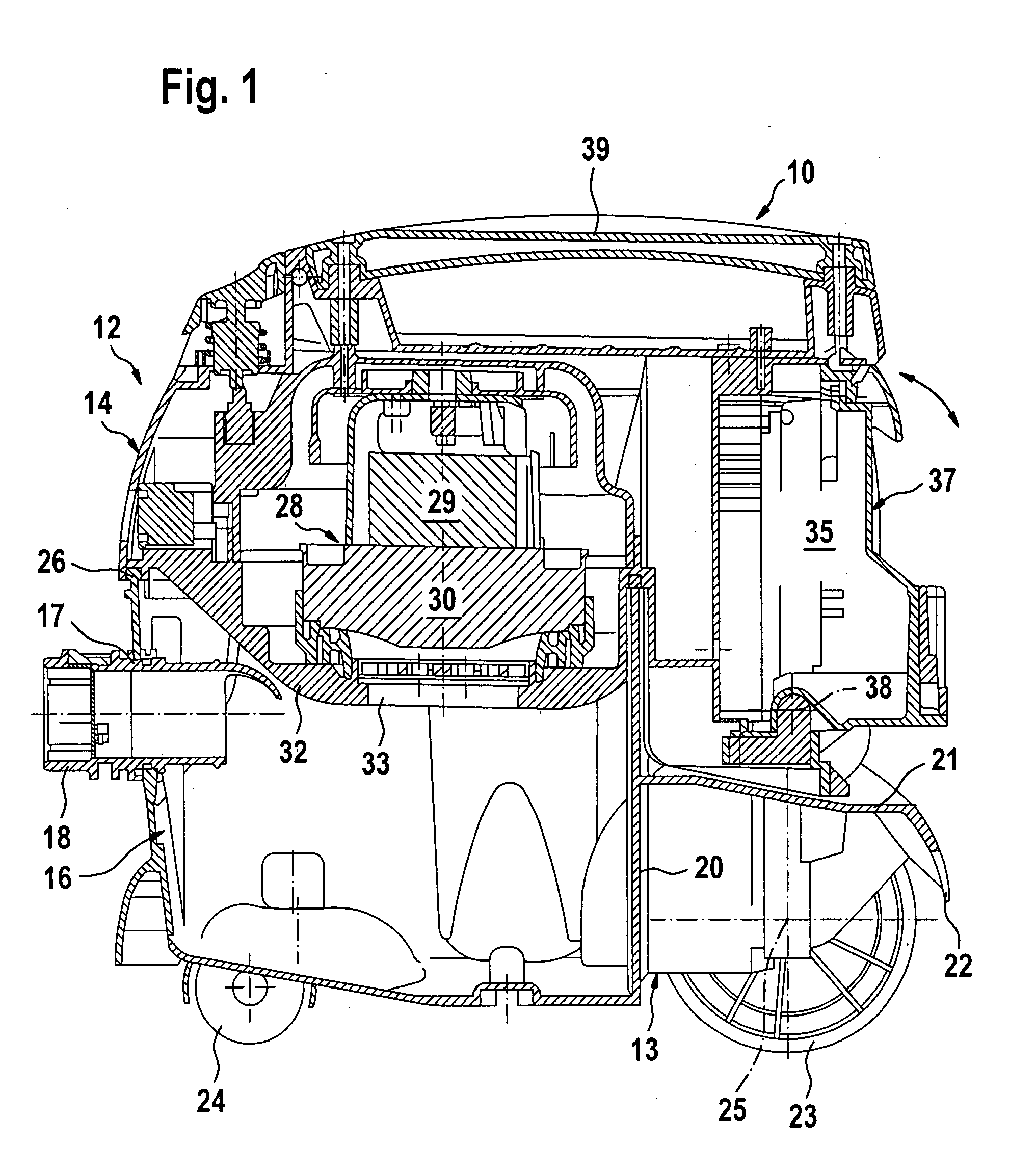
[0037] In the drawing, a cleaning apparatus according to the invention in the form of a suction apparatus 10 is schematically illustrated. Said apparatus comprises a housing 12 having a housing lower part 13 and a housing upper part 14. The housing lower part 13 forms a dirt-collection container 16 with a suction inlet 17 through which a suction connection piece 18 passes. A suction hose, which is known per se and therefore not illustrated in the drawing and can carry a suction nozzle at its free end, can be connected to the outside of the suction connection piece 18 in a customary manner. A step 21, which is oriented in a substantially horizontal manner and carries a downwardly directed protection wall 22 at its free end, is integrally formed on the rear face 20 of the dirt-collection container 16 approximately halfway up the dirt-collection container, said rear face being directed away from the suction connection piece 18. Two running wheels are mounted on the housing lower part 1...


PUM

PropertyMeasurementUnit
voltageaaaaaaaaaa
poweraaaaaaaaaa
mechanicalaaaaaaaaaa

Abstract

The invention relates to a cleaning apparatus comprising a cleaning unit driven by an electric motor and a housing which has a battery chamber for accommodating at least one rechargeable battery, a connecting device having a mechanical mounting part and an electrical plug connector part being disposed in the battery chamber for establishing an electrical and mechanical connection between the battery and the cleaning apparatus. In order to further develop said cleaning apparatus in such a way that batteries of different physical shapes can be used, the invention proposes that the mounting part is detachably mounted in the battery chamber, and the plug connector part is detachably connectable as desired to the mounting part or to a chamber wall of the battery chamber.

Description

[0001] This application is a continuation of international application number PCT / EP2005 / 012654 filed on Nov. 26, 2005. [0002] The present disclosure relates to the subject matter disclosed in international application number PCT / EP2005 / 012654 of Nov. 26, 2005 and German application number 10 2005 007 923.7 of Feb. 11, 2005, which are incorporated herein by reference in their entirety and for all purposes.BACKGROUND OF THE INVENTION [0003] The invention relates to a cleaning apparatus, in particular a suction apparatus, comprising a cleaning unit driven by an electric motor and comprising a housing which has a battery chamber for accommodating at least one rechargeable battery, a connecting device having a mechanical mounting part and an electrical plug connector part being disposed in the battery chamber for establishing an electrical and mechanical connection between the battery and the cleaning apparatus. [0004] Cleaning apparatuses of this type can be used to clean a surface, fo...

Claims


Application Information

Patent Timeline
Patent Type & Authority Applications(United States)
IPC IPC(8): H02B1/00H01M50/202H01M50/204H01M50/247H01M50/264H01M50/296
CPCA47L9/2884A47L9/2878H01M2/1022Y02E60/10H01M50/204H01M50/264H01M50/247H01M50/202H01M50/296
Inventor FRANK, JUERGENHENSEL, MAICLEPOLD, HOLGER
Owner ALFRED KARCHER GMBH & CO KG
Why Eureka
Try Eureka