Closure device for shoe

Active Publication Date: 2008-03-20
SKECHERS US II
View PDF45 Cites 27 Cited by
  • Summary
  • Abstract
  • Description
  • Claims
  • Application Information

AI Technical Summary

Benefits of technology

[0016]The position of the second and third crossing of the shoe tongue by the interlaced strap is designed to evenly disperse the force of the interlaced strap across the wearer's foot effectively providing the greatest amount

Problems solved by technology

The disadvantage of the conventional shoe lace is that it requires an excessive amount of time for adjustment.
Furthermore, if at any given time the shoe upper needs to be adjusted for better comfort, all laces, above the point at which the adjustment must be made, must be unfastened to adequately reach the point of adjustment, and refastened after the adjustment is made.
In addition the shoe lace system has a tendency to unfasten itself as the knot is inadvertently undone.
Often this shortcoming is relieve

Method used


Image

  • Closure device for shoe
  • Closure device for shoe
  • Closure device for shoe

Examples


Embodiment Construction

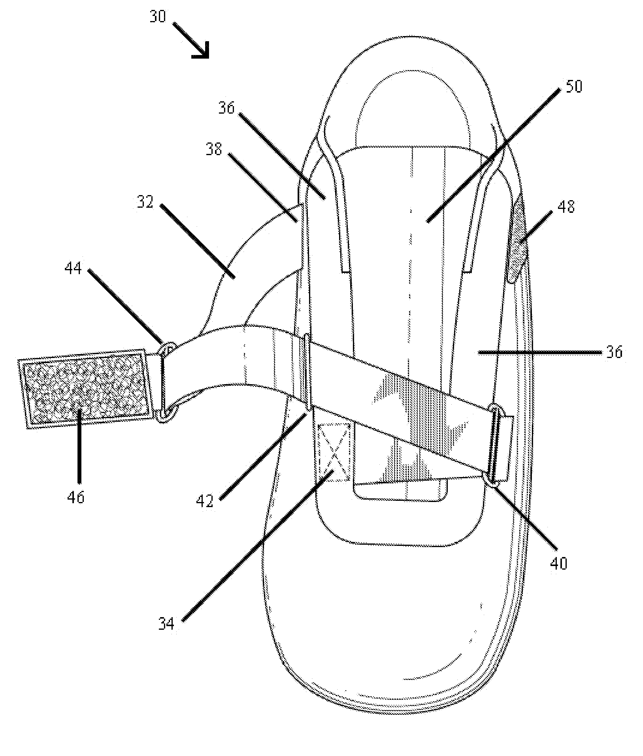
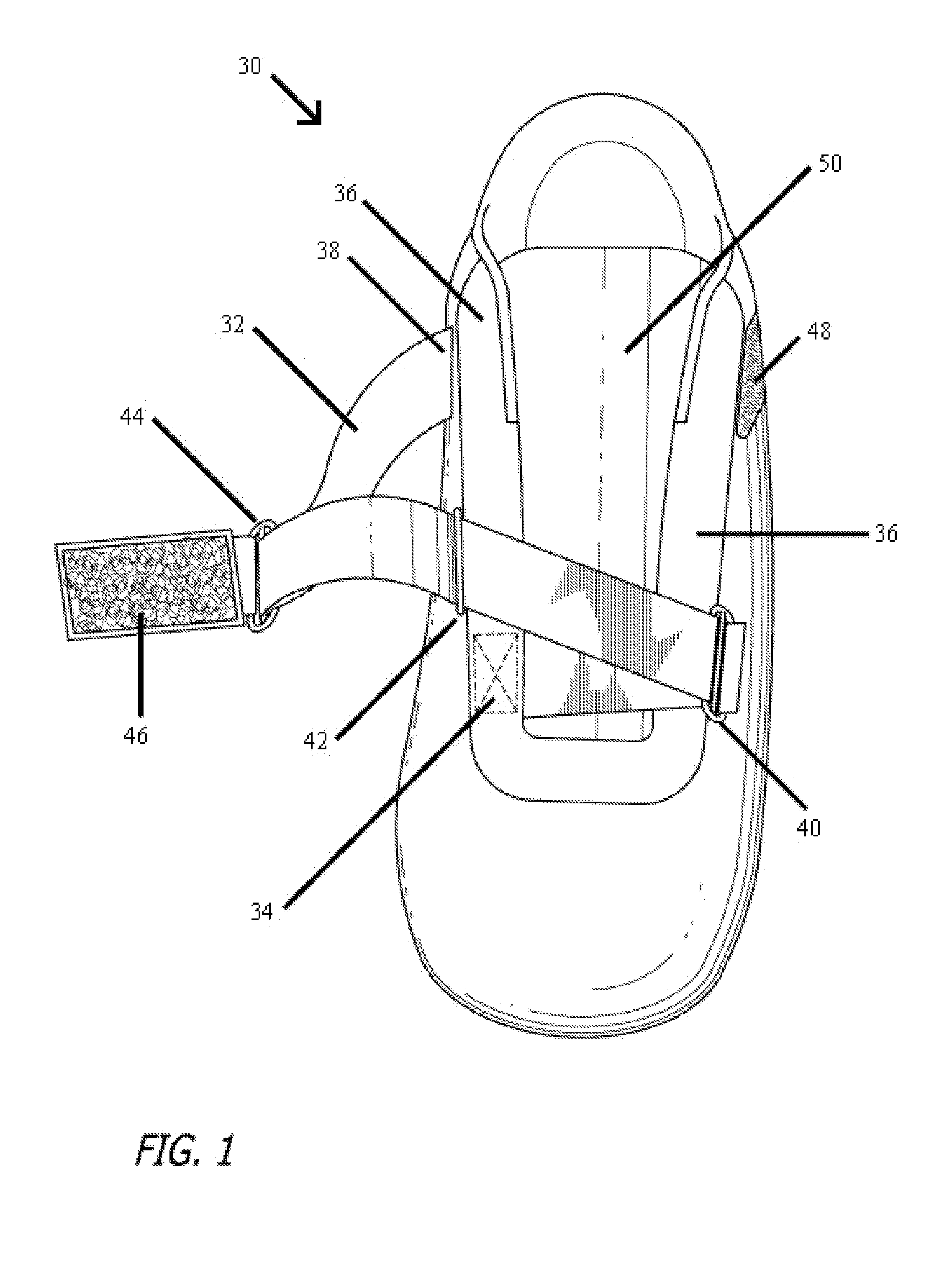
[0021]The invention will now be described with reference to FIG. 1, which illustrates a top view of the preferred embodiment of a shoe upper portion in accordance with the present invention. As shown in FIG. 1, a shoe upper 30 has a u-shaped member 36 and a tongue 50 spanning below the u-shaped member 36. In a conventional shoe the u-shaped member 36 would have an eyerow which would contain numerous openings for the passage of shoe laces. The present invention contains an interlaced strap 32 positioned to encompass the u-shaped member 36. The interlaced strap 32 is connected at the bottom of the u-shaped member 36 at the lower fixed point 34 found on the medial side of the shoe upper 30. The interlaced strap 32 crosses the u-shaped member 36 to the lateral d-ring 40 across the tongue 50, back across the tongue 50 to the medial d-ring 42, through the adjustable d-ring 44 and attaches to the shoe upper at the upper fixed point 38.

[0022]With further reference to FIG. 1, the adjustable ...


PUM


Abstract

The present invention provides a fitted, supportive, comfortable shoe upper with a laceless closure device comprising one interlaced strap capable of rapid adjustment in multiple planes of movement.

Description

BACKGROUND OF THE INVENTION[0001]1. Field of the Invention[0002]The present invention relates to footwear, more particularly to a laceless shoe upper closure device with adjustability.[0003]2. Description of the Related Art[0004]The modern consumer of sport footwear expects a comfortable, supportive, functional, tastefully ornamented product. Footwear designers have responded with products combining new materials and performance engineering features. The adoption of alternative closure mechanisms to the conventional shoe lace has lead to the use of straps, buckles, and other innovations to adapt the shoe upper to the individual end users foot and to allow for quicker fitting and removing of a shoe. The present invention relates to a laceless shoe upper closure device capable of being adjusted to better fit the end users foot.[0005]Prior art closure mechanisms have included the conventional shoe lace system, multi-strap devices, and other variants. Attempts have been made to improve ...

Claims


Application Information

Patent Timeline
IPC IPC(8): A43C11/00
CPCA43C11/1493
Inventor KELLEY, SCOTT
Owner SKECHERS US II
Why Eureka
Try Eureka