Light-weight photovoltaic system

a photovoltaic system and light weight technology, applied in the direction of photovoltaics, solar heat collector mounting/support, solar heat collector safety, etc., can solve the problems of system dependent on gravity cannot be employed on a light roof structure, significant damage to the cover as well as the insulation of the roof, etc., to achieve the effect of improving durability

Inactive Publication Date: 2008-03-20
SOLON SE
View PDF15 Cites 66 Cited by
  • Summary
  • Abstract
  • Description
  • Claims
  • Application Information

AI Technical Summary

Benefits of technology

[0012]It is, therefore, a general object of the invention to provide a lightweight photovoltaic system of improved durability under adverse weather conditions.
[0013]A more specific object of the invention resides in providing a photovoltaic system of improved wind stability.
[0016]Yet another object of the invention is to provide a lightweight photovoltaic system capable of resisting being lifted off under extreme wind conditions.
[0019]While retaining the known advantages of prior art lightweight systems such as, in particular, ease of mounting, placement even on weak substructures, pressure, weather and fire resistance, the photovoltaic system in accordance with the invention additionally ensures that any suction wind loads of the kind occurring under normal weather conditions are safely and effectively absorbed. Lift off of the inventive photovoltaic system is assuredly prevented by the provision of a common module panel and the anchoring thereof by a simple tension wire system at at least two positions. Furthermore, in the arrangement in accordance with the invention, the structure of the lightweight planar member is such that water collecting on the substructure can run off effectively.
[0022]In the context of the photovoltaic system in accordance with the invention, when attaching the module panel of a substructure, it is deemed to be especially advantageous to place the module panel on the substructure in immediate engagement therewith. This avoids the need for a gap between the substructure and the lightweight panel member to provide for pressure balancing. To be mounted, the lightweight panel members may be placed directly upon the substructure and pushed against each other. Care must, however, be taken when placing a panel directly upon the substructure to ensure that any water which may collect on the substructure can flow off unimpededly. To this end, while the material of the lightweight planar members in accordance with the invention is actually water-repellent, the panels themselves are pervious to water. They may be of a porous structure as is known from drainage panels. Thus, water running off would flow through the entire lightweight planar members. In principle, the structure should accommodate the volume of water which may collect. Of course, the water-pervious structure must be sufficiently strong not imperil the stability of the self-supporting lightweight planar members and the photovoltaic panel superposed thereon. Similar results may be yielded by appropriately profiling the substructure-engaging lower surface of the lightweight planar member. Such profiling may include a wide range of freely selectable patterns, orientations and cross-sections. For instance, the profiling may be provided by elongated grooves of semicircular, rectangular or preferably truncated cross-section placed at a predetermined distance from, and, if desired, crisscrossing, each other. In such a structure of crisscrossing grooves the points of intersection in the surface of a lightweight planar member would still provide sufficient strength and stability to support the overall weight of the module panel.

Problems solved by technology

Therefore, significant point or distributed loads are generated in the area of force transmission between the supports of the photovoltaic system and the cover of the roof cover which can significantly damage the cover as well as the insulation of the roof.
A different problem may result from the photovoltaic systems being usually mounted in a horizontal disposition, forming a wind tunnel between the lower surface of the system and the surface of the substructure which causes additional lifting forces to be introduced into the system.
Yet another problem arises in connection with inherent load reserves of the substructure which usually is the roof structure.
Hence, a system depending on gravity cannot be employed on a light roof structure.
However, the through-bores reduce the pressure resistance of the lightweight boards.
However, this reduces the effective photovoltaic surface.
These relatively complex measures taken in addition to those proposed by U.S. Pat. No. 5,746,839 clearly indicate that securing a lightweight structural system on a substructure without directly engaging it to prevent lift off under suction wind loads is rather problematic indeed.

Method used


Image

  • Light-weight photovoltaic system
  • Light-weight photovoltaic system
  • Light-weight photovoltaic system

Examples


Embodiment Construction

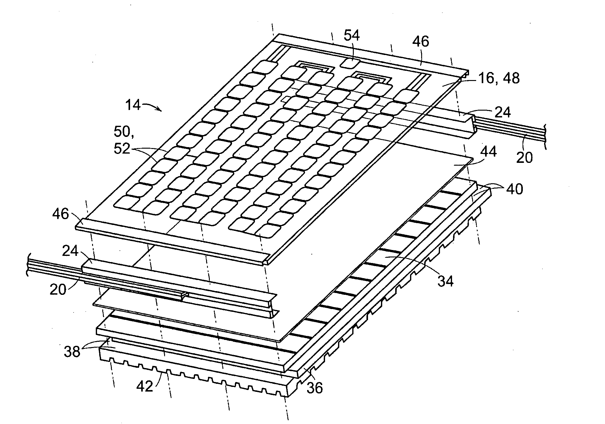
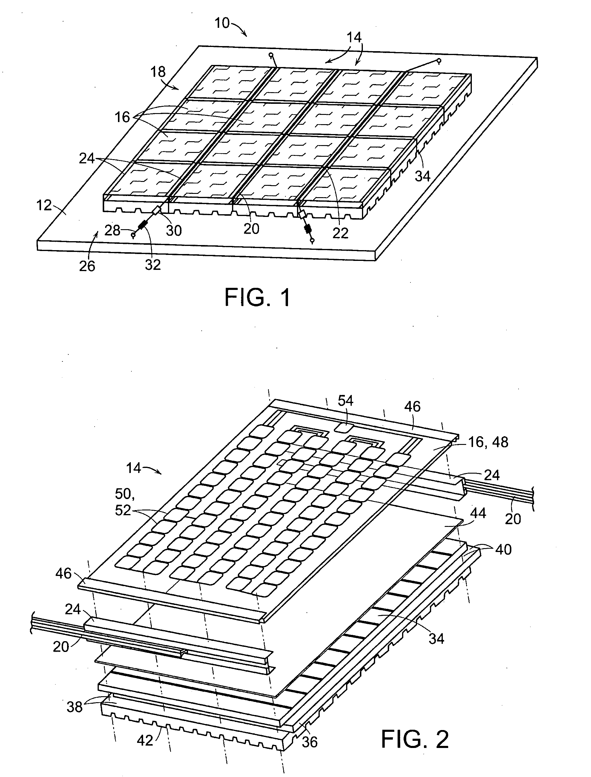
[0033]FIG. 1 depicts a lightweight photovoltaic system 10 placed on a substructure 12 in direct engagement therewith. The schematically depicted substructure 12 may, for instance, be a flat roof of a building (not shown). As shown, the photovoltaic system 10 consists of sixteen substantially rectangular individual photovoltaic modules 14 arranged in horizontal rows and vertical columns and supporting photovoltaic panels 16. By rigidly interconnecting all of the photovoltaic modules 14, a stable rectangular module panel 18 is formed in the manner of a matrix from all the rows and columns of individual photovoltaic modules 14. Any occurring loads and stresses are safely absorbed by and distributed over the matrix. The system 10 is mounted on the substructure 12 in direct engagement therewith. Each photovoltaic module 14 is a prefabricated one and consists of a rectangular photovoltaic panel 16 mounted on a substantially rectangular board 34 to be described. For assembling the module p...


PUM


Abstract

A light-weight photovoltaic system made from a plurality of substantially rectangular photovoltaic modules consisting of a lightweight support board and a photovoltaic panel disposed in abutting relationship in rows and columns on a substrate and connected to each other by a dovetailing arrangement between frames connecting the support board to the panel with clamping strips holding down the photovoltaic panel on the frame and of at least one tension wire extending along one of the rows and columns at attached to a substructure for retaining the system thereon.

Description

BACKGROUND OF THE INVENTION[0001]1. Field of the Invention[0002]The invention, in general, relates to a lightweight photovoltaic system consisting of a plurality of photovoltaic modules arranged in rows and columns and, more particularly, to a system of the kind referred to including a plurality of photovoltaic modules consisting of photovoltaic panels disposed over a self-supporting flat and lightweight boards of water-repellant material for mounting at a predetermined distance from a substructure. Preferably, the self-supporting boards of the system engage each other in a gapless arrangement and are held together by guide and connecting fixtures including a frame and a wire tension system.[0003]2. The Prior Art[0004]Among renewable energy sources photovoltaic systems can be applied in many ways not least because of their modular construction from individual photovoltaic modules. Nowadays, their main field of application relates to consumer applications, i.e., they are used to tran...

Claims


Application Information

Patent Timeline
Patent Type & Authority Applications(United States)
IPC IPC(8): H01L31/048
CPCF24J2/4614F24J2/5241Y02B10/12H02S20/23Y02E10/52H02S20/00Y02E10/47F24S25/50F24S40/44Y02E10/50Y02B10/10
Inventor SCHWARZE, SASCHA OLIVER
Owner SOLON SE
Why Eureka
Try Eureka