
Hydraulically driven tractor

a hydraulic drive and tractor technology, applied in the direction of drilling machines and methods, percussion drilling, drilling machine/well accessories, etc., can solve the problems of coiled tubing being susceptible to helical buckling, damaging the coiled tubing itself, and most tractors that are currently available are somewhat incompatible with coiled tubing equipmen

Inactive Publication Date: 2008-03-20
SCHLUMBERGER TECH CORP
View PDF32 Cites 58 Cited by
  • Summary
  • Abstract
  • Description
  • Claims
  • Application Information

AI Technical Summary

Benefits of technology

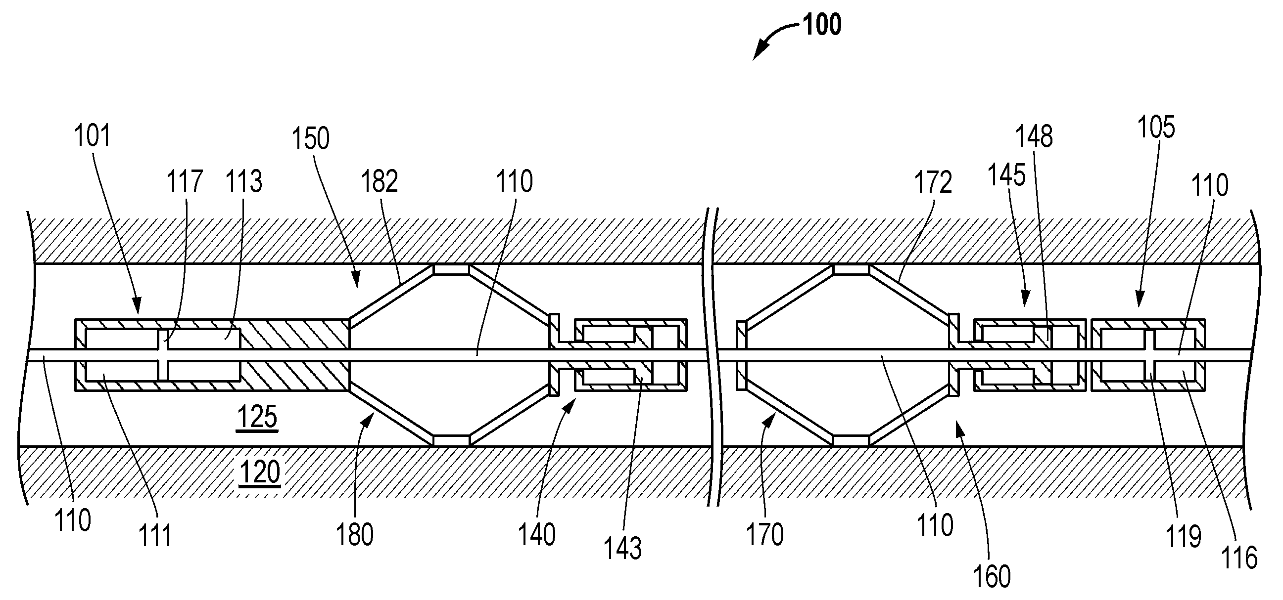
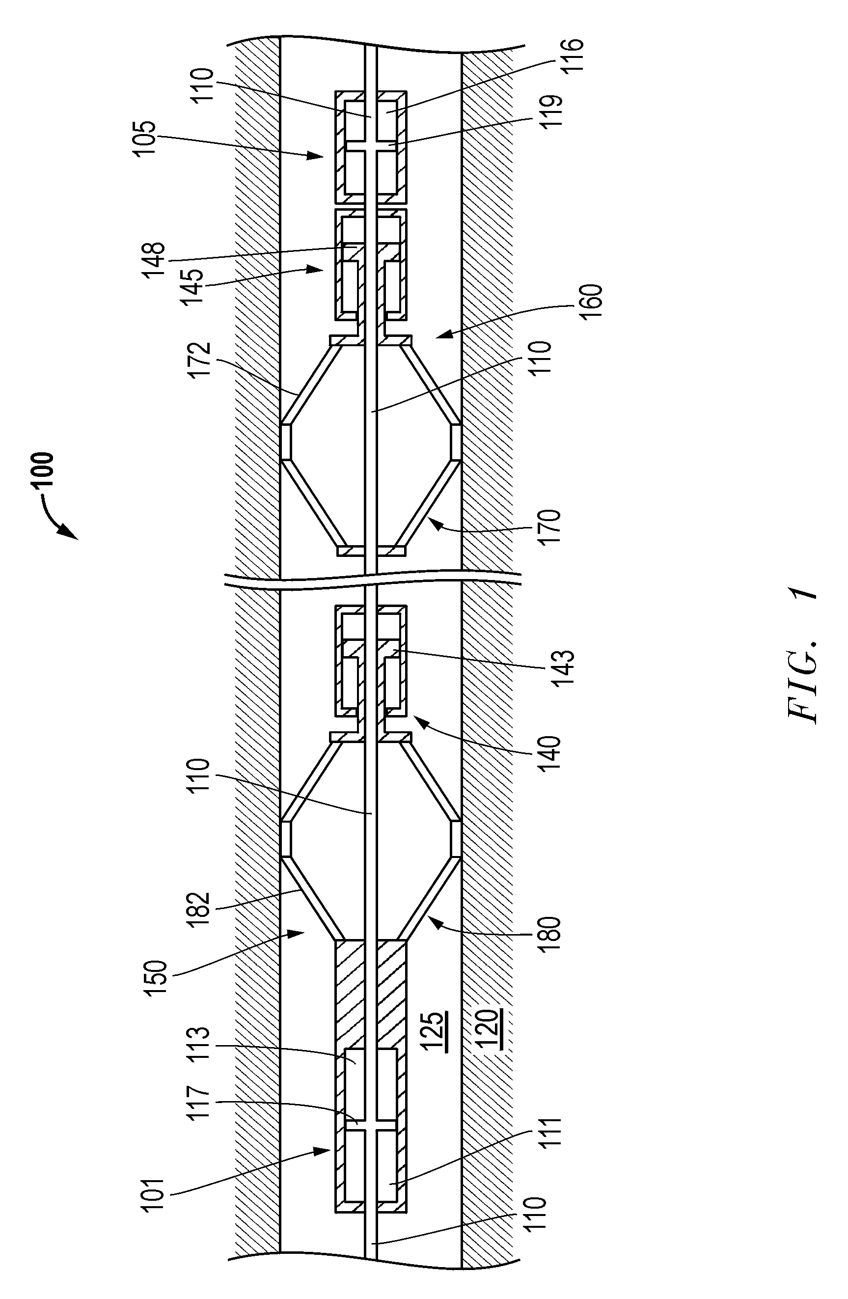
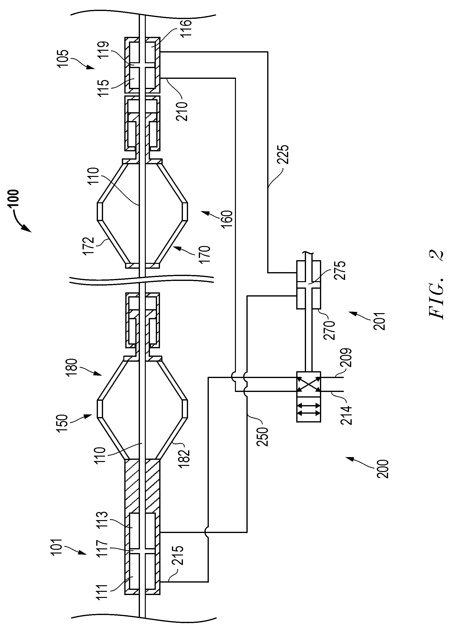
[0009]A hydraulically driven tractor may also be provided that includes an uphole assembly and a downhole assembly, each having anchors for immobilization thereof. A plurality of pilot operated valves may be coupled to each of the anchors for selectively deactivating immobilization of one of the anchors to provide lateral mobility to its associated assembly.

Problems solved by technology

Unfortunately, the coiled tubing is susceptible to helical buckling as it is pushed deeper and deeper into the well.
In such circumstances, continued downhole pushing on the coiled tubing simply lodges it more firmly into the well wall ensuring its immobilization (i.e. coiled tubing “lock-up”) and potentially damaging the coiled tubing itself.
Unfortunately, most tractors that are currently available are somewhat incompatible with coiled tubing equipment from a powering standpoint.
However, unless the inner diameter of the coiled tubing is undesirably increased, this reduces the available internal flow space of the coiled tubing.
However, in this case significant obstacles to the manufacture of the coiled tubing itself may be presented.
Furthermore, regardless of the exact positioning, the addition of a separate electric cable may significantly increase the total weight of downhole equipment, given that the well depths involved are likely in the neighborhood of several thousand feet.
Additionally, given the independent nature of the coiled tubing and an electric cable, other challenges may be presented in attempts to maintain compatible tensions and control simultaneously through such separate lines of equipment.
Unfortunately, however, the removal of electronic control from the tractor has left configurations of hydraulic tractors that fail to advance in a continuous manner through the well.
Whether it be failure to maintain continuous advancement of the reciprocating tractor or failure to provide reliable anchoring during tractor advancement, currently available and contemplated configurations of large scale hydraulic tractors remain substantially deficient in terms of continuous downhole advancement.
Thus, the total achievable coiled tubing depth attainable with current hydraulic tractors remains limited.

Method used


Image

  • Hydraulically driven tractor
  • Hydraulically driven tractor
  • Hydraulically driven tractor

Examples


Embodiment Construction

[0016]Embodiments are described with reference to certain downhole tractors for use in an oil well. In particular, dual anchor reciprocating double armed embodiments are described. However, a variety of configurations may be employed. Regardless, embodiments described may include the ability to advance downhole in a continuous manner, maintaining downward movement and substantially avoiding static friction. In fact, certain embodiments may also maintain a degree of anchoring at all times during advancement so as to avoid the occurrence of spring-back as detailed below.

[0017]Referring now to FIG. 1 an embodiment of a hydraulically driven tractor 100 is shown disposed within a production region 120 of a well 125. The tractor 100 may be directed to this location to aid in hydrocarbon recovery efforts from the production region 120. The tractor 100 has adjacent assemblies 150, 160 that each includes a housing 101, 105, an anchor 170, 180 and actuators 140, 145 therefor. A piston 110 is ...


PUM


Abstract

A large scale hydraulically driven downhole reciprocating tractor to display substantially continuous advancement. The tractor may be configured to pull coiled tubing downhole in a continuous manner so as to substantially avoid static frictional resistance to the pulling. As a result, the tractor and coiled tubing may achieve up to about twice the depth into the well otherwise attainable. Additionally, the tractor may include a fail safe mechanism whereby a plurality of pilot operated valves are employed to ensure that immobilization of at least one anchor of the tractor is present at all times during downhole advancement to thereby avoid the undesired effects of coiled tubing spring-back.

Description

REFERENCE TO RELATED APPLICATION(S)[0001]This Patent Document claims priority under 35 U.S.C. §119(e) to U.S. Provisional Application Ser. No. 60 / 883,115, entitled Flow Driven Coiled Tubing Tractor, filed on Jan. 2, 2007 which is incorporated herein by reference.FIELD OF THE INVENTION[0002]Embodiments described relate to tractors for pulling coiled tubing and other equipment through an underground well. In particular, embodiments of tractors are described for pulling equipment downhole in a continuous reciprocating manner.BACKGROUND OF THE RELATED ART[0003]Coiled tubing operations may be employed at an oil field to deliver a downhole tool to an operation site for a variety of well intervention applications such as well stimulation, the forming of perforations, or the clean-out of debris from within the well. Coiled tubing operations are particularly adept at providing access to highly deviated or tortuous wells where gravity alone fails to provide access to all regions of the wells....

Claims


Application Information

Patent Timeline
IPC IPC(8): E21B23/08E21B4/00
CPCE21B4/18E21B2023/008E21B23/14E21B23/001
Inventor SHEIRETOV, TODORPRIETO, CECILIATUNE, GOKTURKHILL, STEPHEN D.
Owner SCHLUMBERGER TECH CORP
Learn More