Spectrophotometer

a spectrophotometer and light-receiving element technology, applied in the field of spectrophotometers, can solve the problems of large measurement errors, increased noise-to-signal ratio, and structural complication, and achieve the effect of reducing the amount of electric charge and lowering the signal strength of the light-receiving elemen

Inactive Publication Date: 2008-03-20
SHIMADZU CORP
View PDF3 Cites 6 Cited by
  • Summary
  • Abstract
  • Description
  • Claims
  • Application Information

AI Technical Summary

Benefits of technology

[0013]In view of the above circumstances, it is an object of the present invention to provide a technique of reducing an amount of electric charge to be accumulated in a light-receiving ...

Problems solved by technology

That is, the lowered signal strength leads to an increase in noise-to-signal ratio which causes larger measurement errors.
On the other hand, this technique has a problem about structural complication and high cost of the control circuit for independently controlling the sw...

Method used


Image

  • Spectrophotometer
  • Spectrophotometer
  • Spectrophotometer

Examples


Embodiment Construction

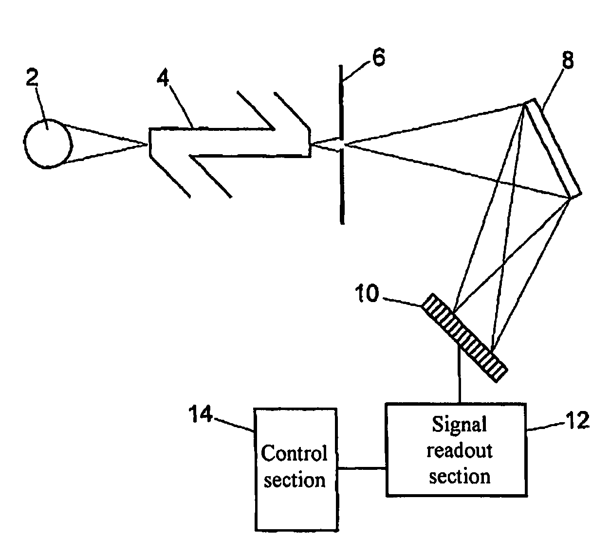
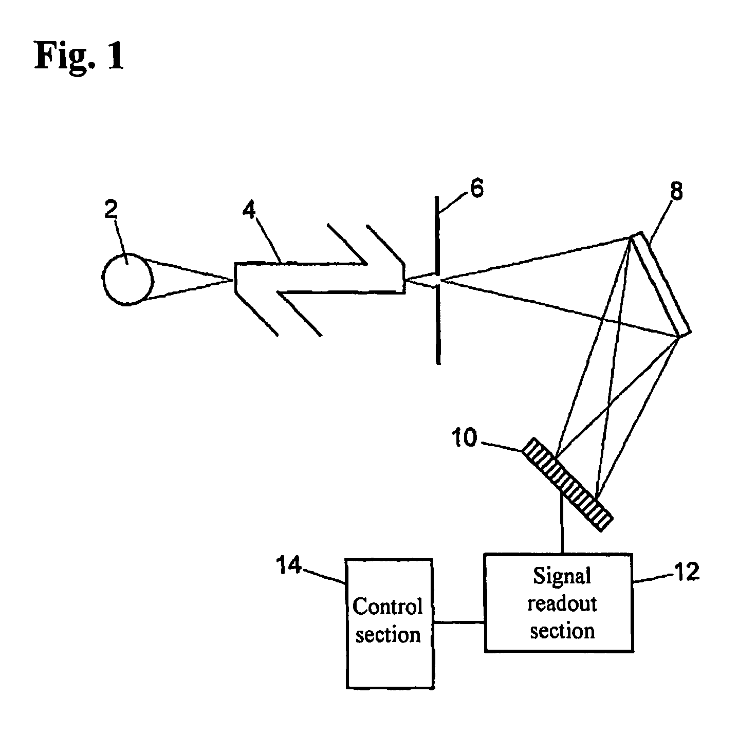
[0031]FIG. 1 is a schematic block diagram showing a spectrophotometer according to one embodiment of the present invention, wherein the spectrophotometer is used for a liquid chromatography measurement.

[0032]In this embodiment, the spectrophotometer is designed such that measurement light is emitted from a light source 2 comprising a D2 lamp and a W lamp, to a flow cell (sample chamber) 4 having therein a flow of an eluate from a liquid-chromatographic column, so as to measure an absorbance. The light transmitted through the flow cell 4 is formed as a line-shaped beam through a slit. Then, the line-shaped beam is spectrally dispersed into its light components with respect to each wavelength region through a wavelength dispersion element 8, and the spectral light components are entered into a photodiode array 10. The photodiode array 10 comprises a plurality of light-receiving elements each composed of a photodiode and arranged in corresponding relation to respective spectral light c...


PUM


Abstract

A spectrophotometer, in which an emission spectrum of the light source is measured. Based on the measured emission spectrum, a threshold is set to allow only an outstanding spectral intensity in a specific wavelength region to be greater than the threshold. Then, a ratio between the setup threshold and a peak spectral intensity in the specific wavelength region greater than the threshold is calculated. Then, an electric-charge accumulation time for a light-receiving element corresponding to a wavelength region equal to or less than the threshold is set at an upper limit of electric-charge accumulation time causing no saturation in any light-receiving element. Based on the ratio between the threshold and the peak spectral intensity in the specific wavelength region greater than the threshold, an electric-charge accumulation time for the light-receiving element corresponding to the specific wavelength region greater than the threshold is set.

Description

BACKGROUND OF THE INVENTION[0001]1. Field of the Invention[0002]The present invention relates to a spectrophotometer which comprises an optical system for spectrally dispersing measurement light, a photodiode array having a plurality of light-receiving elements arranged in corresponding relation to respective spectral light components dispersed by the optical system and each adapted to receive and photoelectrically convert a corresponding one of the spectral light components, a sample chamber disposed in a light path of the measurement light, and a signal readout section for reading out an amount of electric charge accumulated in each of the light-receiving elements of the photodiode array.[0003]2. Description of the Related Art[0004]In a spectrophotometer using a photodiode array having a plurality of light-receiving elements (photodiodes) arranged along a spectral direction, measurement light is spectrally dispersed into its light components with respect to each wavelength region ...

Claims


Application Information

Patent Timeline
IPC IPC(8): G01J3/28
CPCG01J3/027G01J3/36G01J3/10
Inventor FUJITA, TAKESHI
Owner SHIMADZU CORP
Why Eureka
Try Eureka