

Method and system for detecting operator alertness
- Summary
- Abstract
- Description
- Claims
- Application Information
AI Technical Summary
Benefits of technology
Problems solved by technology
Method used
Image

Examples
Embodiment Construction
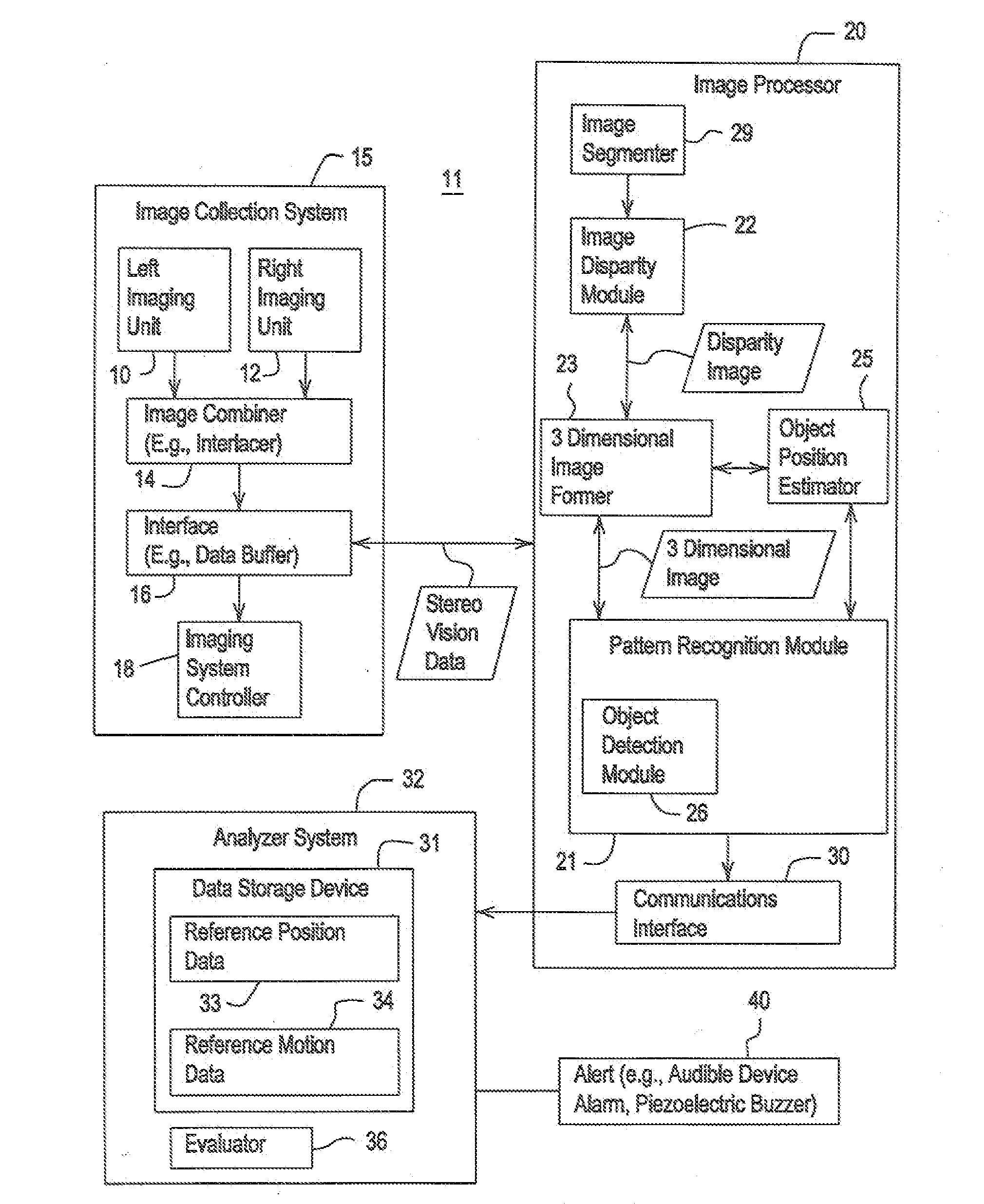
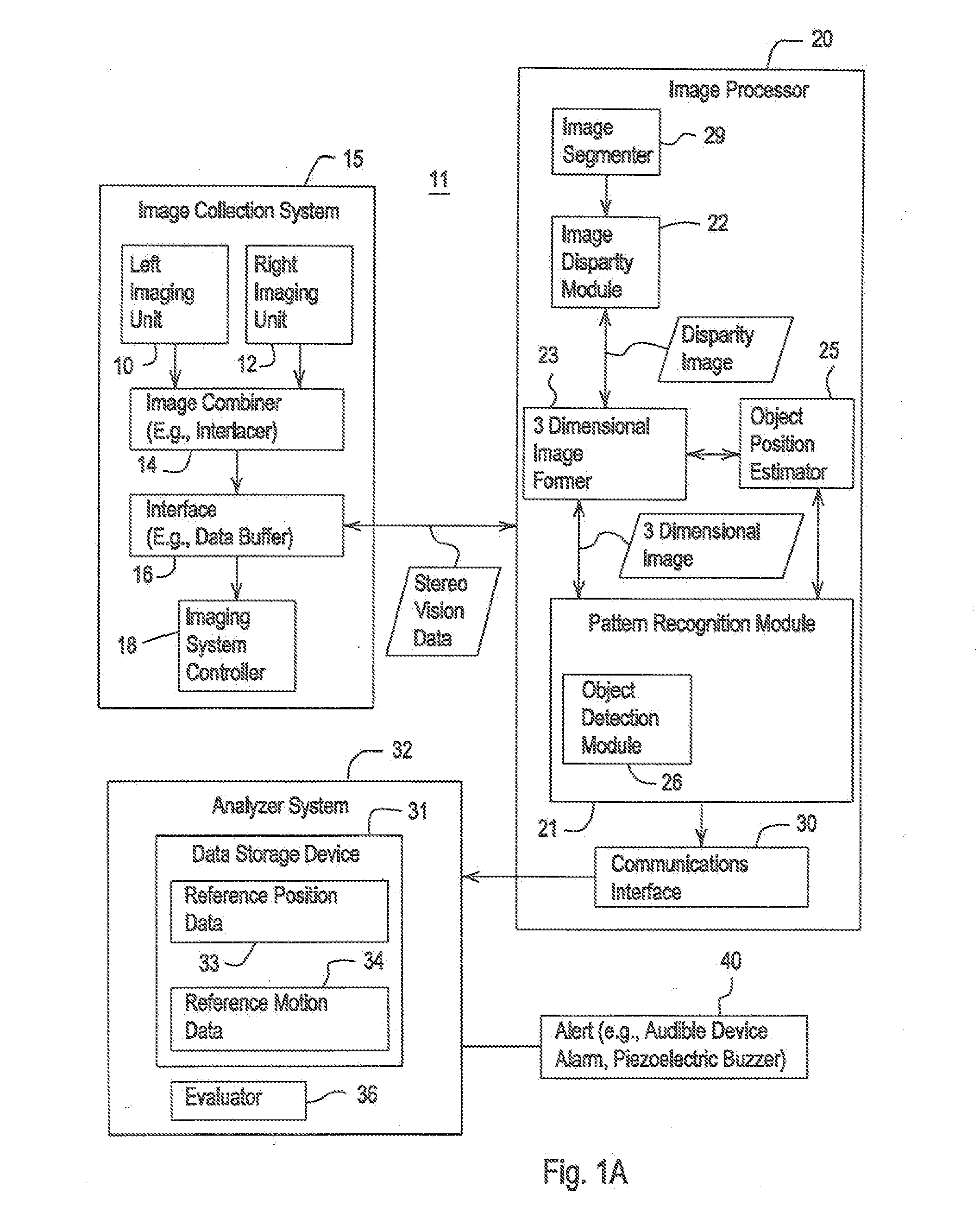
[0016]In accordance with one embodiment FIG. 1A illustrates a detection system 11 for detecting an alertness or inattentiveness of an operator. As used herein, the operator generally refers to the operator of any vehicle or any machine. The vehicle may comprise any train, bus, airplane, aircraft, helicopter, ship, boat, watercraft, automobile, truck, tractor, combine, agricultural equipment, construction equipment, forestry equipment, earth-moving machinery, mining equipment, or the like. The vehicle may have, but need not have, unmanned, semi-autonomous, or autonomous capabilities with respect to guidance and navigation. For example, the vehicle may have a guidance system that uses a location-determining receiver (e.g., a Global Positioning System receiver with differential correction) to determine a location of a vehicle to facilitate guidance of a vehicle in accordance with a path plan.
[0017]The detection system 11 comprises an image collection system 15 coupled to an image proce...
PUM
 Abstract
Description
Claims
Application Information