

Medical devices and methods of making and using
- Summary
- Abstract
- Description
- Claims
- Application Information
AI Technical Summary
Problems solved by technology
Method used
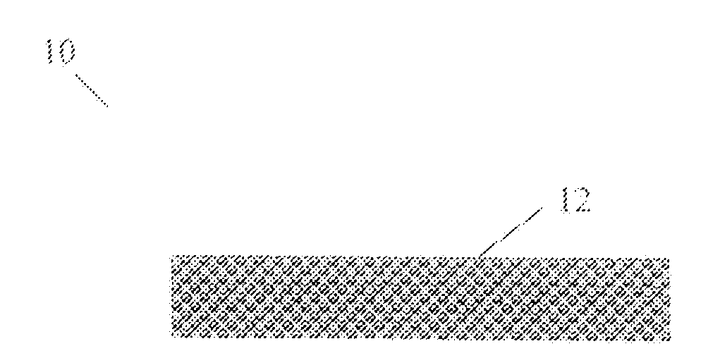
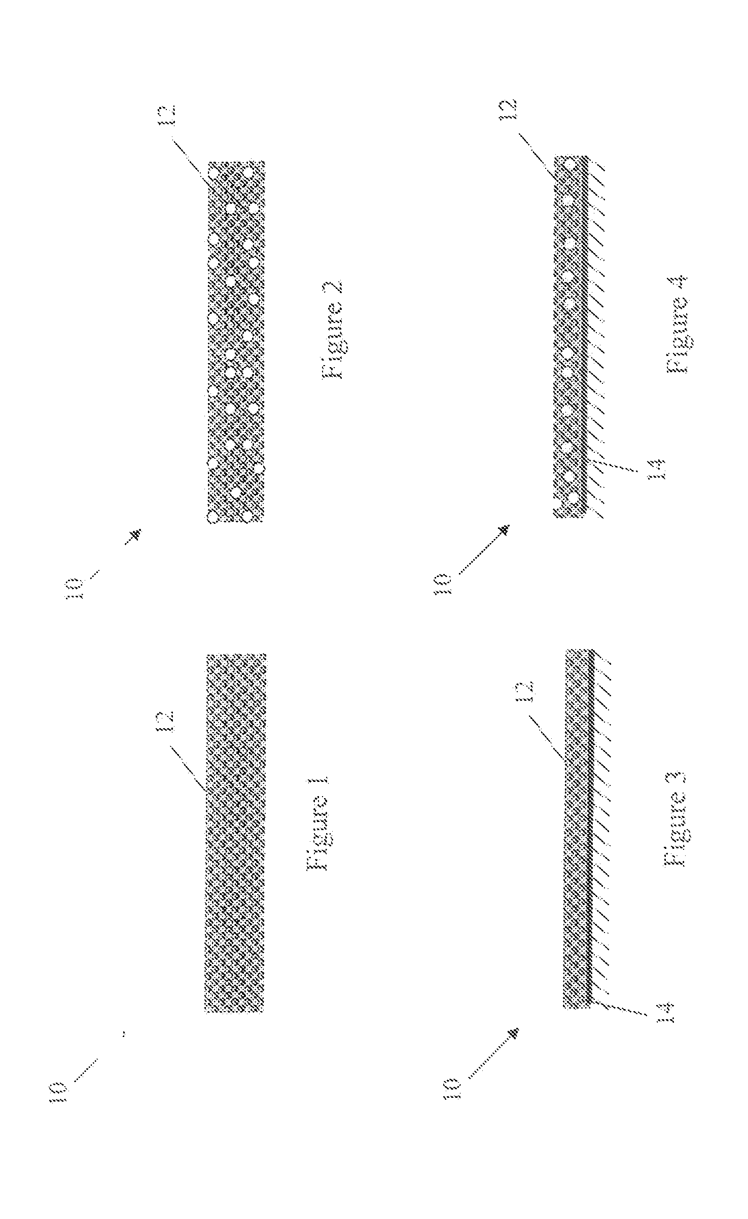
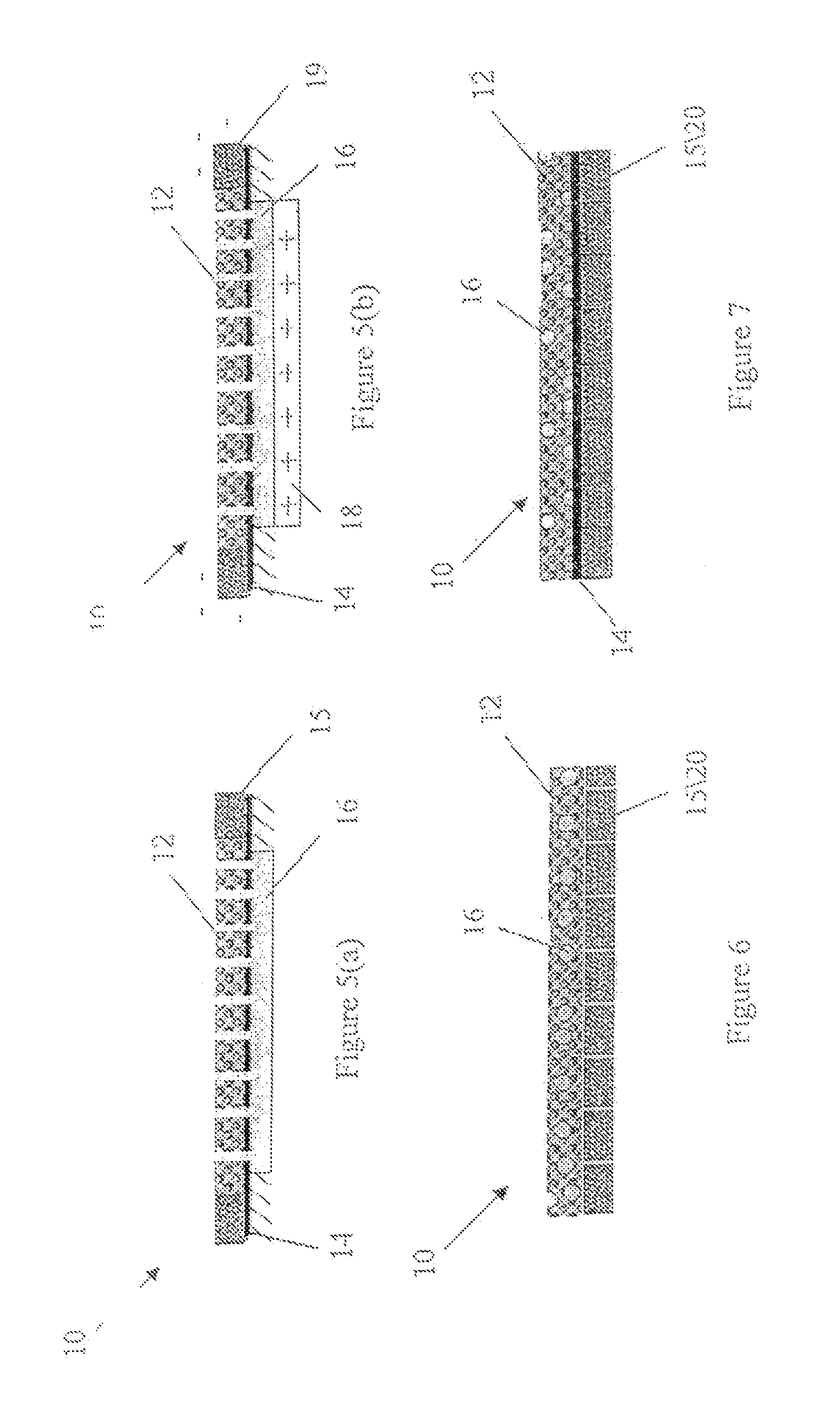
Image

Examples
example 1
Formation of a Dense Composite Oxide Layer via Air Plasma Spray
[0074] A composite of spray dried powder spheres having an overall composition of 13 wt % TiO2, 13 wt % Y2O3, 10 wt % ZrO2, 6 wt % CeO2, and the balance of Al2O3 (commercially available from Inframat Corp. under the tradename of NANOX S2613), was used as a feedstock. The feedstock was plasma thermal sprayed. using a Metco 9MB plasma spray system (all Metco products mentioned herein are sold by Sulzer Metco Ltd.), onto a metal substrate which had been sandblasted using alumina granules prior to thermal spraying. A mixture of argon and hydrogen gases was used in conjunction with a GH-type nozzle (Metco) to generate a hot and high-velocity plasma flame. The powder-feeding rate was between about 1.5 to about 2.0 pounds per hour (lb / hr), which corresponded to a deposition rate of about 50 to about 120 micrometers (μm) per pass. The substrate was preheated to a temperature of about 120 degrees Celsius (° C.), which was mainta...
example 2
Formation of a Dense Al2O3 Layer via Air Plasma Spray
[0088] Angular, fused, and crushed Al2O3 powder (Metco 105SFP) was used as a feedstock. The feedstock was plasma thermal sprayed using a Metco 9MB plasma spray system, onto a metal substrate which had been sandblasted using alumina granules prior to thermal spraying. A mixture of argon and hydrogen gases was used in conjunction with a GP-type nozzle (Metco) to generate a hot and high-velocity plasma flame. The powder-feeding rate was between about 2.0 to about 2.5 lb / hr, which corresponded to a deposition rate of about 50 to about 120 μm per pass. The substrate was preheated to a temperature of about 120° C., which was maintained during the spray process when a small standoff distance and low gun traverse speed were selected. Representative plasma spraying parameters for the dense Al2O3 layer were as follows:
[0089] Plasma gases: [0090] Primary gas: Argon (100 PSI, 100 SCFH) [0091] Secondary gas: H2, (50 PSI)
[0092] Plasma power:...
example 3
Formation of a Dense Composite Oxide Layer via Air Plasma Spray
[0102] A composite of spray dried powder spheres having an overall composition of Cr2O3-5SiO2-3TiO2 (Metco 136F) was used as a feedstock. The feedstock was plasma thermal sprayed, using a Metco 9MB plasma spray system, onto a metal substrate which had been sandblasted using alumina granules prior to thermal spraying. A mixture of argon and hydrogen gases was used in conjunction with a GH-type nozzle (Metco) to generate a hot and high-velocity plasma flame. The powder-feeding rate was between about 2.5 to about 3.0 lb / hr, which corresponded to a deposition rate of about 15 to about 30 μm per pass. The substrate was preheated to a temperature of about 120° C., which was maintained during the spray process when a small standoff distance and low gun traverse speed were selected. A cross-cooling jet was used to cool the substrate with an air flow at about 40 PSI. Representative plasma spraying parameters for the dense compos...
PUM
 Abstract
Description
Claims
Application Information