Techniques for Cooling Solar Concentrator Devices

a technology of solar concentrator and concentrator cell, which is applied in the direction of semiconductor devices, basic electric elements, electrical equipment, etc., can solve the problems of limiting the power level capacity of solar concentrator devices, waste heat that has to be removed, and limiting the amount of heat that is transferred from the solar converter cell to the heat sink

Inactive Publication Date: 2009-04-02
IBM CORP
View PDF5 Cites 19 Cited by
  • Summary
  • Abstract
  • Description
  • Claims
  • Application Information

AI Technical Summary

Benefits of technology

[0008]The present invention provides solar concentrator devices and techniques for the fabrication thereof. In one aspect of the invention, a solar concentrator device is provided. The solar concentrator device comprises at least one solar converter cell; a heat sink; and a liquid metal between the solar converter cell and the heat sink, configured to thermally couple the solar converter cell and the heat sink during operation of the device. The solar converter cell can comprise a triple-junction semiconductor solar converter cell fabricated on a germanium (Ge) substrate. The heat sink can comprise a vapor chamber heat sink. The liquid metal can comprise a gallium (Ga) alloy and have a thermal resistance of less than or equal to about five square millimeter degree Celsius per Watt (mm2° C. / W).

Problems solved by technology

One factor, however, that limits the power level capacity of solar concentrator devices is heat management.
Higher incident solar power levels result in larger amounts of waste heat that have to be removed to prevent overheating of the solar converter cells.
The interface between the solar converter cell and the heat sink, however, can limit the amount of heat that is transferred from the solar converter cell to the heat sink.
For example, since vapor chamber heat sinks generally cannot withstand the temperatures that would be needed to solder attach them directly to the solar converter cells, thermal interface materials (TIMs) are commonly used to thermally couple the solar converter cell with the heat sink.
Common TIMs however do not permit the necessary heat transfer to maintain the solar converter cells at acceptable operating temperatures when incident solar power levels are greater than or equal to about 100 Watts per square centimeter (W / cm2).

Method used


Image

  • Techniques for Cooling Solar Concentrator Devices
  • Techniques for Cooling Solar Concentrator Devices
  • Techniques for Cooling Solar Concentrator Devices

Examples


Embodiment Construction

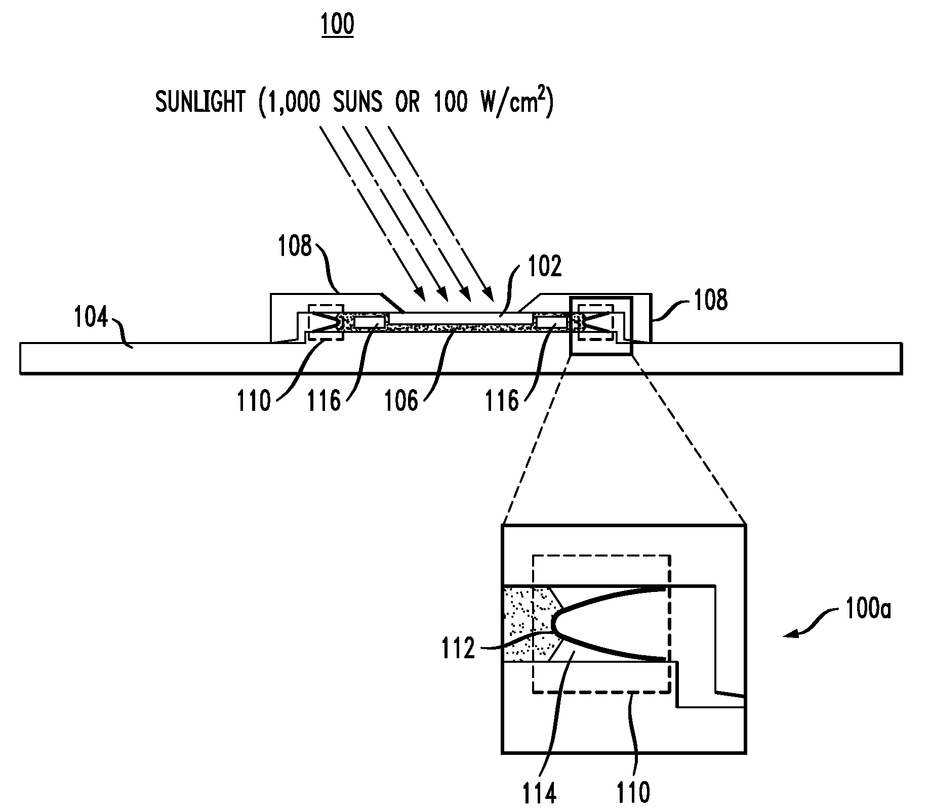
[0017]FIG. 1 is a diagram illustrating a cross-sectional view of exemplary solar concentrator device 100. Solar concentrator device 100 comprises solar converter cell 102, heat sink 104 and liquid metal 106 between solar converter cell 102 and heat sink 104. As will be described in detail below, liquid metal 106 is configured to serve as a thermal interface between solar converter cell 102 and heat sink 104 (i.e., to thermally couple solar converter cell 102 to heat sink 104) during operation of solar concentrator device 100.

[0018]For ease of depiction, FIG. 1 illustrates a solar concentrator device having a single solar converter cell. It is to be understood, however, that multiple solar converter cells may be coupled to a common heat sink. In some instances, having multiple solar converter cells coupled to a common heat sink is preferred, as this configuration results in a reduction in number of parts, costs and production time. Further, the liquid metal thermal interface describe...


PUM


Abstract

Solar concentrator devices and techniques for the fabrication thereof are provided. In one aspect, a solar concentrator device is provided. The solar concentrator device comprises at least one solar converter cell; a heat sink; and a liquid metal between the solar converter cell and the heat sink, configured to thermally couple the solar converter cell and the heat sink during operation of the device. The solar converter cell can comprise a triple-junction semiconductor solar converter cell fabricated on a germanium (Ge) substrate. The heat sink can comprise a vapor chamber heat sink. The liquid metal can comprise a gallium (Ga) alloy and have a thermal resistance of less than or equal to about five square millimeter degree Celsius per Watt (mm2° C./W).

Description

FIELD OF THE INVENTION[0001]The present invention relates to solar concentrator devices, and more particularly, to techniques for cooling solar concentrator devices.BACKGROUND OF THE INVENTION[0002]Increasing energy costs make solar power an attractive alternative to traditional energy sources. One method for converting sunlight into usable electricity is through the use of solar concentrator devices which typically employ mirrors or lenses to concentrate the sunlight onto solar converter cells. The solar cells then convert the sunlight energy into electricity.[0003]Solar concentrator devices are advantageous, as they employ a fewer number of solar converter cells as compared to full panel solar devices. A fewer number of solar converter cells, however, means that for a given output each solar converter cell has to accommodate a higher incident solar power level. For the solar concentrator devices to be practical for widespread implementation, it is also desirable that these devices...

Claims


Application Information

Patent Timeline
Patent Type & Authority Applications(United States)
IPC IPC(8): H01L31/04
CPCH01L31/052H01L31/054Y02E10/52H01L31/0521
Inventor GUHA, SUPRATIKKESSEL, THEODORE GERARDMARTIN, YVES C.
Owner IBM CORP
Why Eureka
Try Eureka