
Grinding Or Polishing Tool For An Oscillating Drive

a technology of oscillating drive and polishing tool, which is applied in the direction of gear teeth manufacturing tools, grinding machines, gear teeth, etc., can solve the problems of small working surface, inability to achieve good polishing or polishing results, and inability to use conventional polishing or polishing tools on oscillating drive such as this one, so as to achieve improved grinding or polishing results

Active Publication Date: 2010-08-19
C & E FEIN GMBH & CO KG
View PDF33 Cites 19 Cited by
  • Summary
  • Abstract
  • Description
  • Claims
  • Application Information

AI Technical Summary

Benefits of technology

The present invention relates to an improved oscillating tool for grinding and polishing that leads to better grinding and polishing results. The invention achieves this by using a larger working surface for the tool, which allows for better surface grinding and polishing. The tool also has a form-locking connection between the driving element and the work spindle of the oscillating drive, which ensures safe power transmission even under high loads. Additionally, the tool has a driving element with high strength and a back element with lower weight, which reduces the mass inertia of the tool and improves grinding and polishing results. The invention also provides a carrier element for the grinding or polishing material, which makes the tool more flexible and easier to use for large-surface operations. The driving element has a Vickers hardness of at least 250 HV, and the maximum hardness preferably being in the range of 840 HV.

Problems solved by technology

In practice it has, however, been found that the use of conventional polishing or grinding tools on oscillating drives of such a kind produces only little abrasion, especially in grinding operations.
As a rule, such tools always have a relatively small working surface, because they are used for special operations and because it is expected that otherwise the grinding results might be impaired or overloading of such oscillating drives might occur.

Method used


Image

  • Grinding Or Polishing Tool For An Oscillating Drive
  • Grinding Or Polishing Tool For An Oscillating Drive
  • Grinding Or Polishing Tool For An Oscillating Drive

Examples


Embodiment Construction

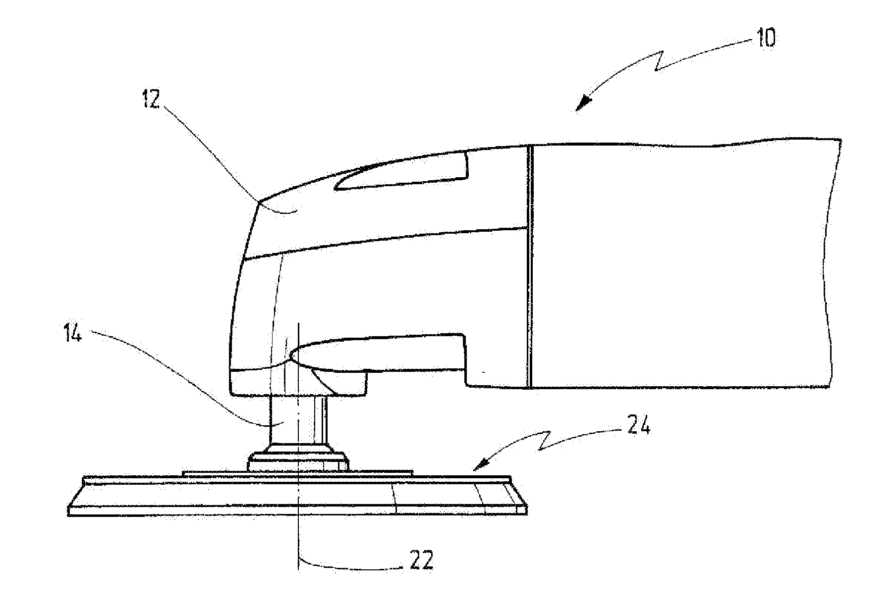
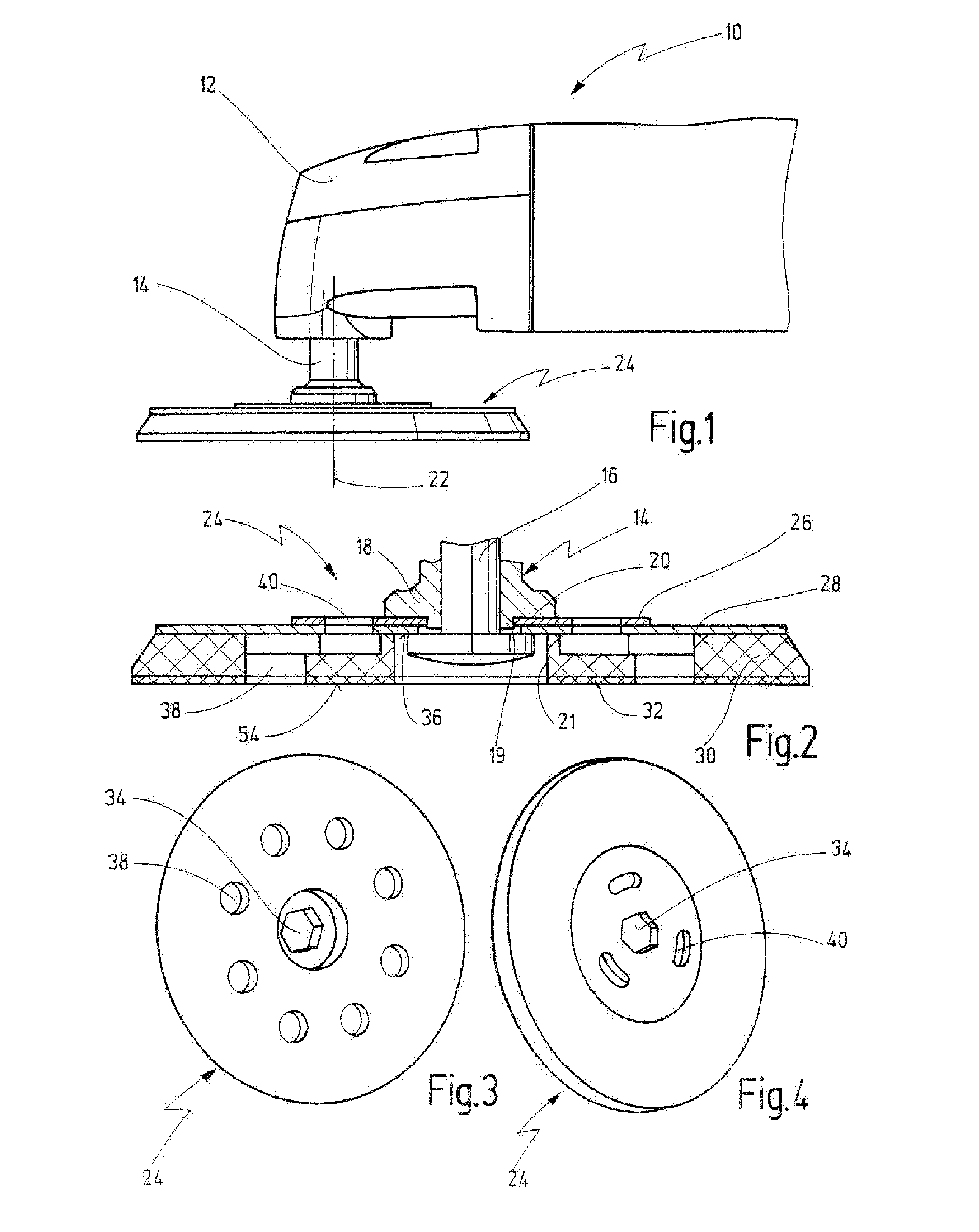
[0067]FIG. 1 shows an oscillating drive of known design, in the area of its gearhead 12, indicated generally by reference numeral 10. The oscillating drive 10 comprises a work spindle 14 that can be driven by an oscillating drive (not shown) to oscillate and to rotate about its longitudinal axis 22. The spindle is driven at a high frequency of, for example, 5000 to 25000 oscillations per minute, and with a small oscillating angle of between approximately 0.5 and 7 degrees. A grinding or polishing tool 24 according to the invention is located on the outer end of the work spindle 14.

[0068]Known oscillating tools offered in the market have relatively small working surfaces, related to the drive power (power input in Watts) or to the total weight (in grams, without the tool).

[0069]For example, the quotient of the working surface and the drive power of oscillating tools offered in the market is between 9.5 and 33.86 mm2 / W, the quotient of the working surface and the weight is between 2.5...


PUM


Abstract

The invention discloses a tool for grinding and polishing, comprising a drive motor, which has a given machine power (rated input power) and by which a work spindle can be driven about its longitudinal axis in rotatingly oscillating fashion, and further comprising a tool-mounting fixture on the work spindle intended to receive a tool that has a working surface for grinding and polishing operations. The quotient of the working surface (in square millimeters) and the rated power input (in Watts) is at least 35 mm2 / W, while the quotient of the working surface and the deadweight (in grams, without the tool) is at least 5.5 mm2 / g.

Description

BACKGROUND OF THE INVENTION[0001]The present invention relates to an oscillating tool having an oscillating drive with a drive motor by which a work spindle can be driven about its longitudinal axis in rotatingly oscillating fashion, wherein the work spindle can be connected with a tool that is equipped with a working surface for grinding or polishing.[0002]An oscillating tool of that kind is known from WO 87 / 02924 A1.[0003]The known oscillating tool comprises an oscillating drive with a work spindle on which a tool in the form of a grinding or polishing tool is secured against independent rotation, for example by a form-locking connection. The oscillating drive moves its work spindle about its longitudinal axis at high frequency and with a small pivoting angle, with the result that especially good grinding results can be achieved, especially when triangular grinding tools with rounded outer edges are used. For, in that case grinding along longitudinal edges and along corners is als...

Claims


Application Information

Patent Timeline
Patent Type & Authority Applications(United States)
IPC IPC(8): B24B23/03B24D7/00B24B55/06
CPCB24B23/02B24B23/04B24B23/03
Inventor THOMASCHEWSKI, WALTERMANN, RAINER
Owner C & E FEIN GMBH & CO KG
Learn More