
Dormer roof ventilator and method thereof

a ventilator and roof technology, applied in ventilation systems, lighting and heating apparatus, heating types, etc., can solve problems such as energy inefficiency, damage to the structural or thermal properties of roof materials, and inability to achieve the effect of improving the ventilation of trapped air

Inactive Publication Date: 2008-03-20
BAY CITIES TIN SHOP INC DBA BAY CITIES METAL PROD
View PDF3 Cites 7 Cited by
  • Summary
  • Abstract
  • Description
  • Claims
  • Application Information

AI Technical Summary

Benefits of technology

[0015]Therefore, it is an object of the present invention to provide a roof ventilator for improved ventilation of trapped air under the roof space of a building.
[0016]It is an object of the present invention to provide a roof ventilator with improved drainage of water around the ventilator.
[0017]It is an object of the present invention to provide a roof ventilator with improved resistance to rust by virtue of its shape.

Problems solved by technology

Roof ventilation is an important consideration in building construction, particularly in home construction because inadequate or poor ventilation can cause condensation problems in the roof and otherwise significantly impair energy efficiency.
Dampness from weather leads to condensation, which can cause damage to the structural or thermal properties of the roofing material.
Another common problem is energy inefficiency in a home due to poor heat ventilation in the attic.
The attic space of a home typically traps heat, whether externally from the sun or internally from a heating unit, which can result in excess heat buildup in the attic space.
Thus, if the antic space becomes too hot, heat is transferred to the rest of the house, thereby requiring more energy consumption to cool the house.
Because such cupola vent is mounted on the ridgeline of a roof, these types of vents do not provide optimal eaves-to-eaves ventilation.
The type of ventilator described by Kolt is not well suited to pitched roofs since, when mounted on the slope of a pitched roof, the vent sits at an angle to the roof and thus is susceptible to allowing rain to enter the roof through the vent.
Moisture problems may be caused by rain entering through the vent.
Rectangular or square dormer vents of the type described in U.S. Pat. No. 2,692,548, in which the ventilation volume is constant, results in poor airflow.
Further, ventilators of the of the type described in U.S. Pat. No. 2,692,548 is also inefficient and costly to manufacture.
This method of fabrication is costly and inefficient because such construction is labor intensive.
Further, ventilators made by welding a plurality of metal sheets are also particularly prone to rusting at the seams.
The unevenness of the welded seams tends to retain moisture deposits that cause accelerated rusting.
Similarly in this regard, ventilators having flat ends tend to allow rainwater to concentrate in the flat area, resulting in rust and eventual deterioration of the back end of the vent.
Not least, ventilators made from a mismatch of metal sheets invariably result in an unattractive construction, which detracts from the appearance of the roof.

Method used


Image

  • Dormer roof ventilator and method thereof
  • Dormer roof ventilator and method thereof
  • Dormer roof ventilator and method thereof

Examples


Embodiment Construction

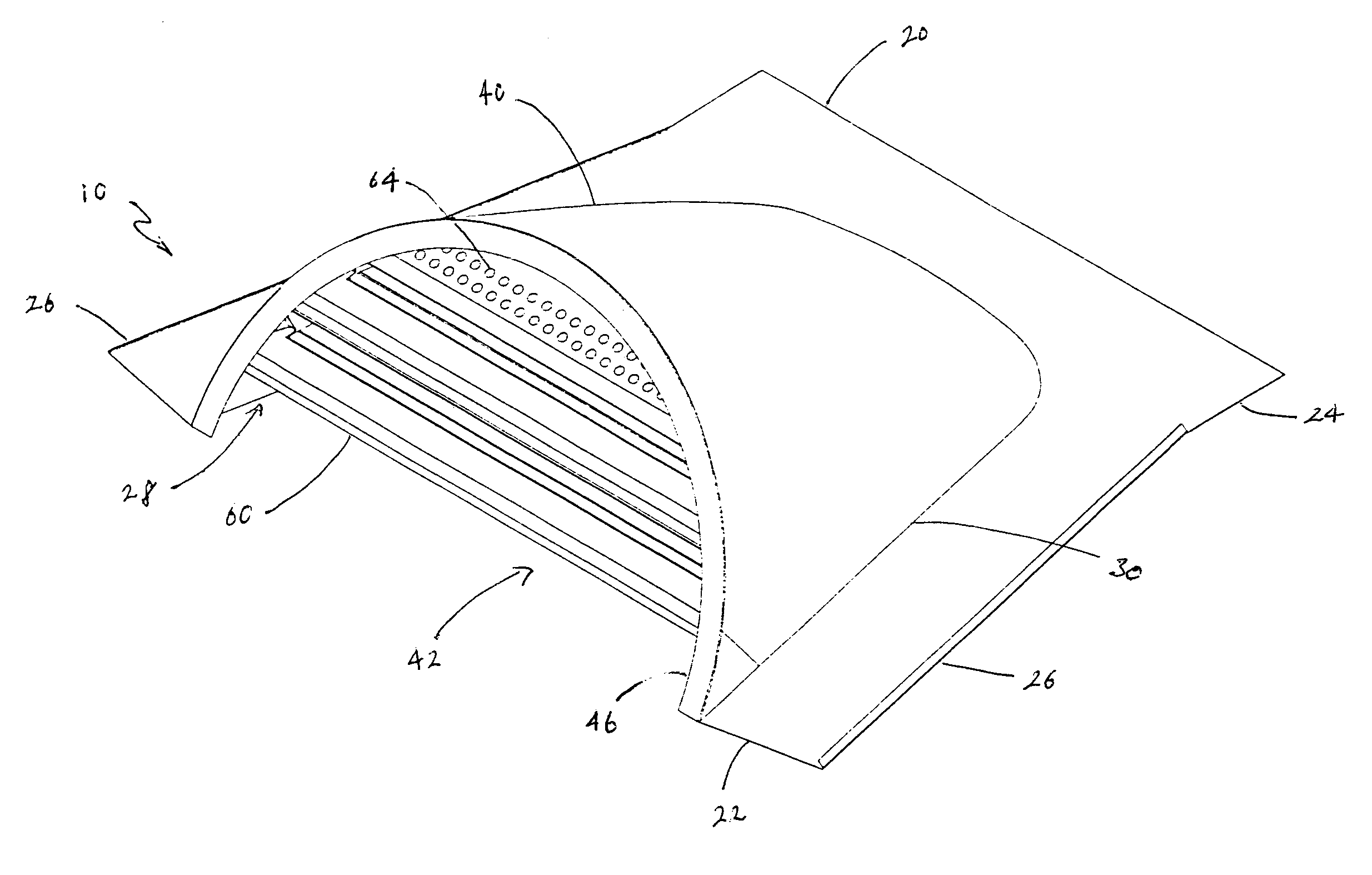
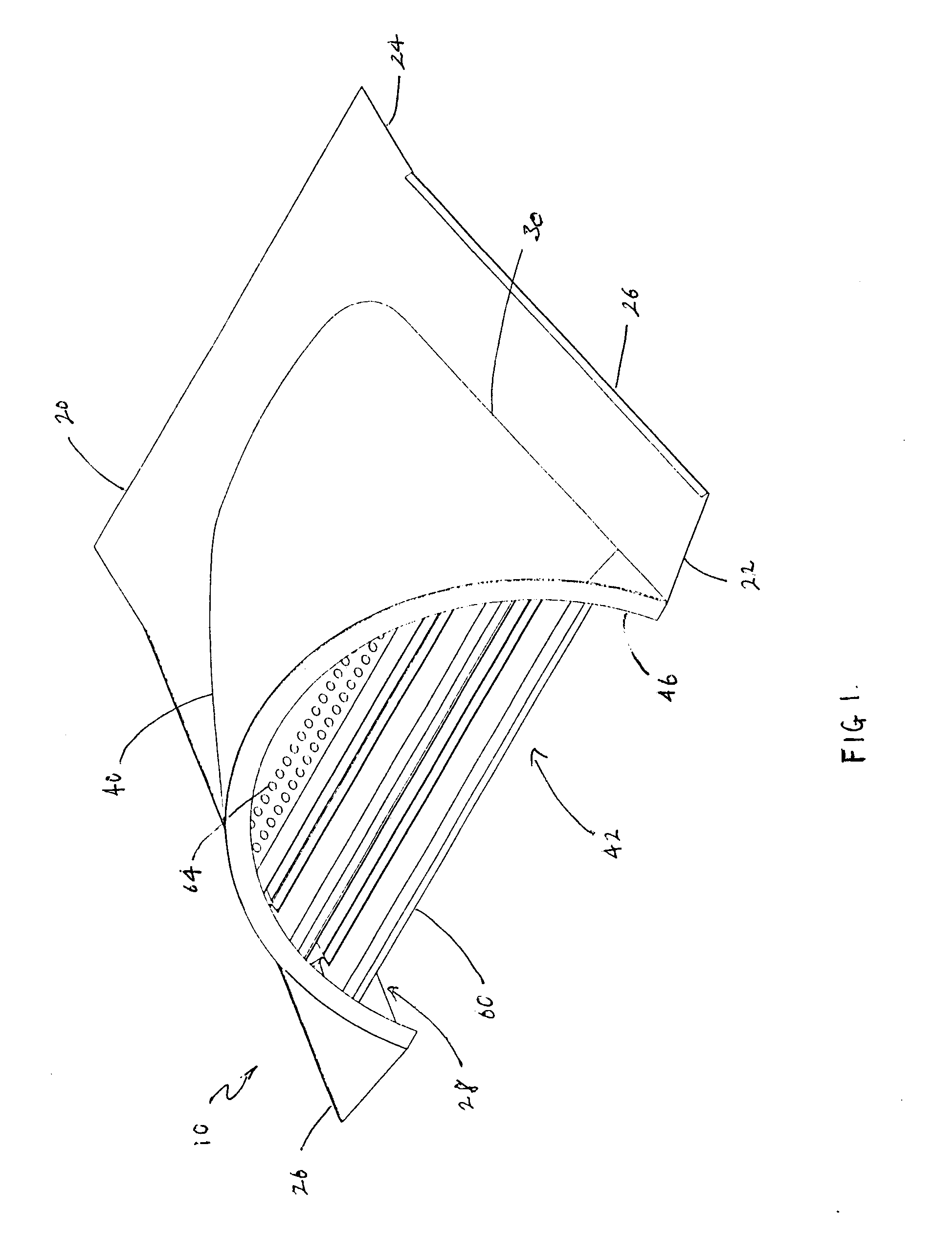
[0037]Referring to FIG. 1, a roof ventilator 10 according to a preferred embodiment of the present invention is shown. Roof ventilator 10 includes generally a base frame 20, a cover 40, and a plurality of louvers or slats 60.

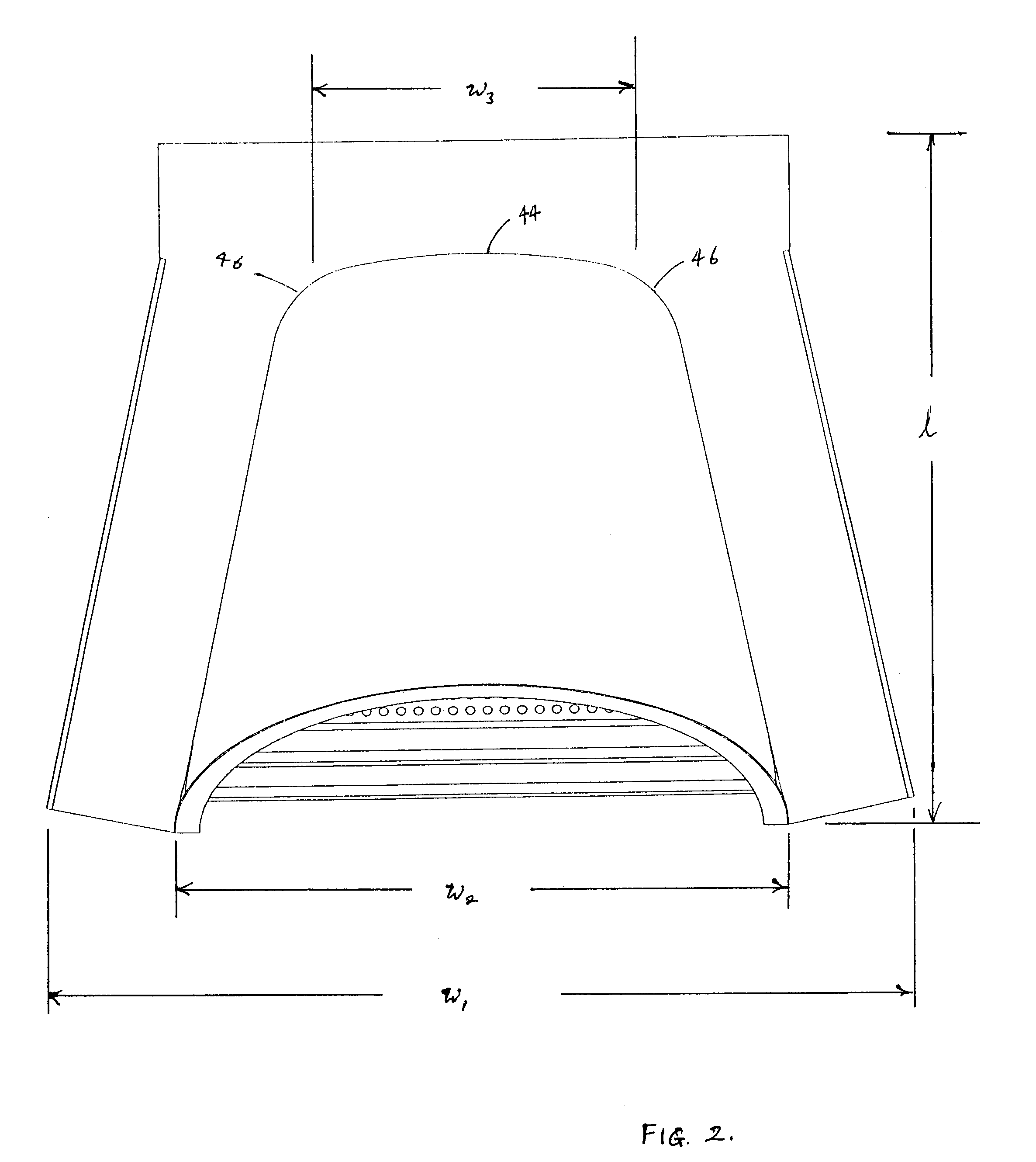
[0038]In the preferred embodiment the base frame 20 includes a front end 22, a rear portion 24, and two side portions 26. As shown in FIG. 1, the front end 22 is wider than the rear portion 24, thus forming generally a trapezoidal shaped frame. By way of example only, the proximate dimensions of the base frame 20 is 28 inches in length (l) and 36 inches wide (w1) as defined in FIG. 2. One of skill in the art would recognize that the roof ventilator 10 can be of any proportionate size so as to accommodate various roof openings.

[0039]The base frame 20 has an opening 28 therein defined by side portions 26 and rear portion 24, the opening 28 adapted to cooperate with an opening in a roof. More specifically, the opening 28 will be defined by the contiguous edge 30 be...


PUM


Abstract

A semiconical shaped roof ventilator comprising a base frame, a cover integrally formed on the base frame and upwardly extending therefrom, the base frame and cover capable of being efficiently manufactured from a single piece of material so as to have improved durability, and wherein the roof ventilator has improved air ventilation due to its semiconical shape.

Description

BACKGROUND OF THE INVENTION[0001]1. Field of the Invention[0002]This invention relates to roof vents, and more particularly to dormer ventilators for pitch roofs.[0003]2. Background Information[0004]Roof ventilation is an important consideration in building construction, particularly in home construction because inadequate or poor ventilation can cause condensation problems in the roof and otherwise significantly impair energy efficiency. Dampness from weather leads to condensation, which can cause damage to the structural or thermal properties of the roofing material. Roof ventilation is necessary to avoid such condensation problems.[0005]Another common problem is energy inefficiency in a home due to poor heat ventilation in the attic. The attic space of a home typically traps heat, whether externally from the sun or internally from a heating unit, which can result in excess heat buildup in the attic space. Excess heat in the attic space can cause the temperature in the rest of the...

Claims


Application Information

Patent Timeline
IPC IPC(8): F24F7/02
CPCE04D2001/309E04D1/30
Inventor HENRY, KAMBERG
Owner BAY CITIES TIN SHOP INC DBA BAY CITIES METAL PROD
Learn More