Non-invasive tracking device and method

a tracking device and non-invasive technology, applied in the direction of instruments, navigation instruments, force/torque/work measurement apparatus, etc., can solve the problems of inability to use the method used in research, the tracking device needs to be affixed, and the method is not suitable for a day to day situation for regular patient treatmen

Inactive Publication Date: 2008-03-20
STRYKER EURO OPERATIONS HLDG LLC
View PDF20 Cites 50 Cited by
  • Summary
  • Abstract
  • Description
  • Claims
  • Application Information

AI Technical Summary

Problems solved by technology

One disadvantage of using a surgical navigation system is that tracking devices need to be affixed to a patients' extremity in order for the system to be able to sense the motion of that extremity.
Because these systems are still somewhat invasive, they do not lend themselves to use in ...

Method used


Image

  • Non-invasive tracking device and method
  • Non-invasive tracking device and method
  • Non-invasive tracking device and method

Examples


Embodiment Construction

[0021]The following detailed description primarily uses the foot as an example of a distal end of an extremity. The present invention can also be used with other extremities.

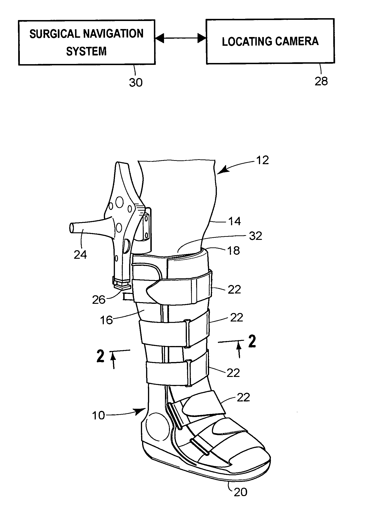
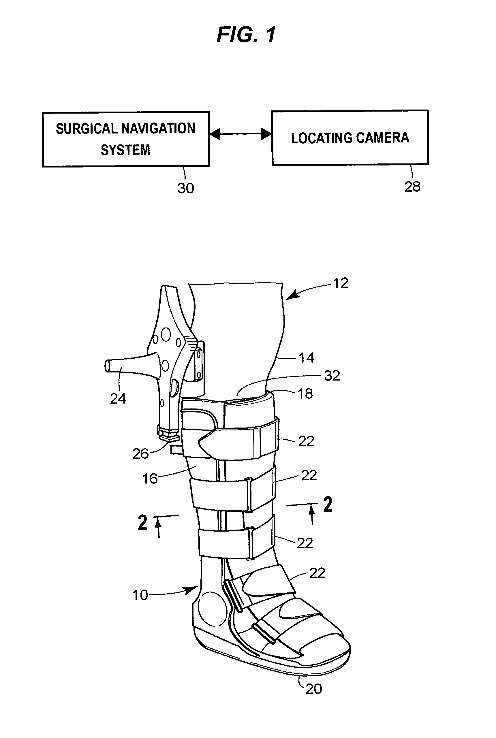
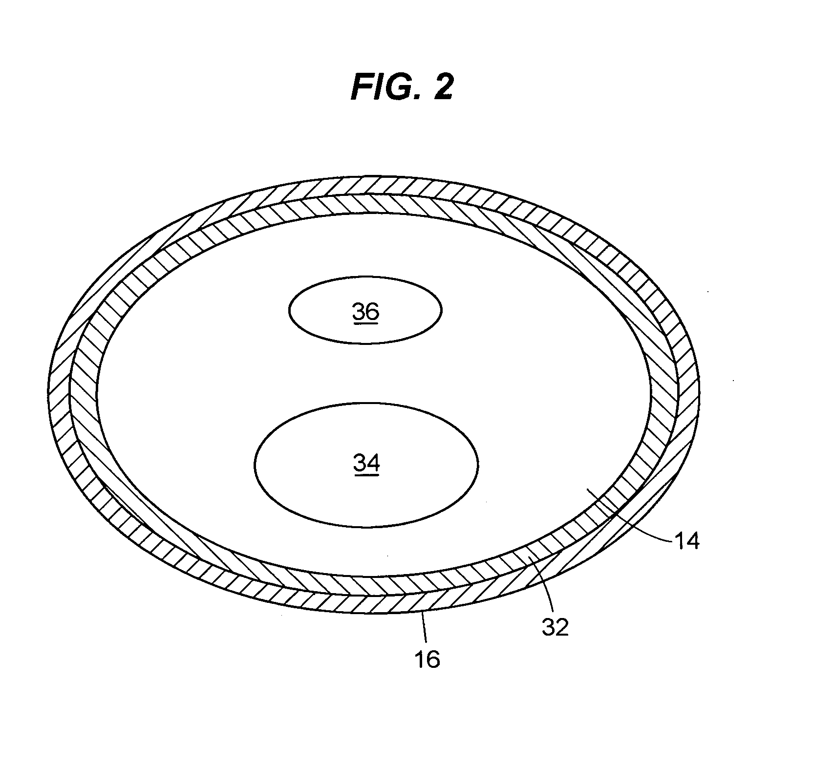
[0022]FIG. 1 shows an embodiment of the present invention that includes a boot 10 worn by patient 12. The boot 10 extends sufficiently far up the leg 14 of the patient 12 so that the boot 10 will move with the leg 14, and more importantly with the tibia within the leg 14 so that there is negligible movement of the boot 10 relative to the leg 14, and in particular the tibia within the leg 14. In this regard, the boot 10 has a body 16 that extends from a proximal end 18 to a distal end 20. The distal end 20 of the body 16 is shaped to immobilize the foot to minimize movement relative to the tibia. In a typical situation, the body 16 will be formed from a rigid material such as hard plastic, stiff leather or structures that include metal reinforcements to immobilize the foot relative to the tibia. In this regard, t...


PUM


Abstract

A device for use with a surgical navigation system includes a body with an inner and outer wall that is shaped to envelope an extremity of a patient, a tracking device associated with the body in a fixed relation to the outer wall of the body, and a filler that fixably conforms to the space between the inner wall of the body and the extremity. The device can be used in orthopedic surgery.

Description

CROSS REFERENCE TO RELATED APPLICATIONS[0001]Not applicableREFERENCE REGARDING FEDERALLY SPONSORED RESEARCH OR DEVELOPMENT[0002]Not applicableSEQUENTIAL LISTING[0003]Not applicableBACKGROUND OF THE INVENTION[0004]1. Field of the Invention[0005]This invention relates to a method to non-invasively establish a meaningful reference frame for a body region relative to which measurements are made. More particularly this invention exploits adjacency properties of the members of the extremities as well as the natural kinematics constraints of their joints to establish important parameters pertaining to the biomechanical axes of the members. Furthermore this invention handles means for temporarily affixing a tracking device at a distal end of an extremity member to enable accurate tracking of the underlying anatomical structures. This invention also describes alternate temporary constraining situations that can be used to establish a rigid transformation between a tracker and the anatomical ...

Claims


Application Information

Patent Timeline
IPC IPC(8): A61B19/00A61B5/11G01C25/00G12B13/00
CPCA61B19/52A61B19/5244G01C21/165A61B2019/5483A61B2019/5251A61B2090/3983A61B90/36A61B34/20A61B2034/2051
Inventor CUELLAR, ALBERTO D.SARVESTANI, AMIRDE LA BARRERA, JOSE MOCTEZUMA
Owner STRYKER EURO OPERATIONS HLDG LLC
Why Eureka
Try Eureka