Expandable support device and methods of use

a support device and expandable technology, applied in the field of expandable support devices for biological implantation, can solve the problems of cement mixture leakage from the bone, entering a dangerous location, spinal canal,

Inactive Publication Date: 2008-03-20
STOUT MEDICAL GROUP
View PDF103 Cites 226 Cited by
  • Summary
  • Abstract
  • Description
  • Claims
  • Application Information

AI Technical Summary

Benefits of technology

[0026] The stent can be delivered using a uni-axial delivery / expansion system, such as those disclosed herein and in the incorporated references herein. The delivery system (i.e., deployment tool) can expand or contract. The deployment tool can have a sliding sheath shaft. The deployment tool can deploy the expandable support device uniformly from both longitudinal ends. Longitudinal compaction of the expandable support device can radially expand the expandable support device.

Problems solved by technology

The cement mixture can leak from the bone, potentially entering a dangerous location such as the spinal canal.
The cement mixture, which is naturally viscous, is difficult to inject through small diameter needles, and thus many practitioners choose to “thin out” the cement mixture to improve cement injection, which ultimately exacerbates the leakage problems.
This further exacerbates the leakage.
The mixture also fills or substantially fills the cavity of the compression fracture and is limited to certain chemical composition, thereby limiting the amount of otherwise beneficial compounds that can be added to the fracture zone to improve healing.
Further more, deploying solids into the weak-walled aneurysm increases the risk of rupturing the aneurysm.
Also, certain configurations of aneurysms, such as those with large necks, or not discernable necks at all, are not good candidates for coil or other solid embolization since there is no natural neck to retain the implanted emboli.

Method used


Image

  • Expandable support device and methods of use
  • Expandable support device and methods of use
  • Expandable support device and methods of use

Examples


Embodiment Construction

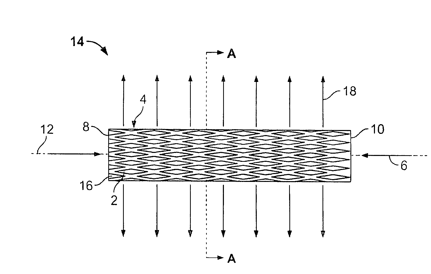
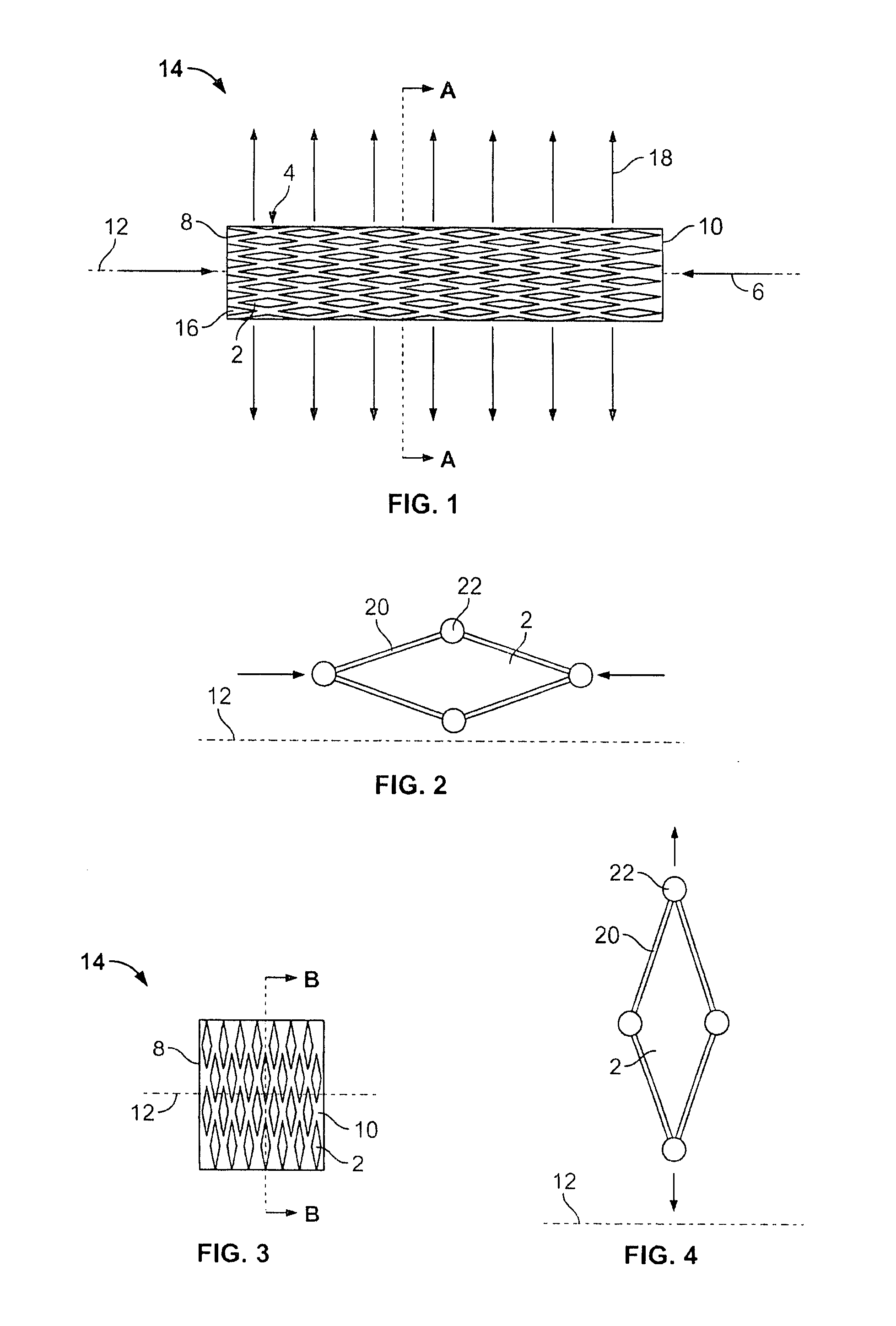
[0089]FIG. 1 illustrates the expandable support device 14 in a contracted configuration. The expandable support device 14 can have a device first end 8 and a device second end 10. The device first end 8 and the device second end 10 can be at opposite longitudinal ends of the expandable support device 14. The expandable support device 14 can have an expandable support device wall 16. The expandable support device 14 can be configured as a cylinder. The expandable support device 14 can have one or more cells. The cells can be holes or voids in the expandable support device wall 16. The cells can be aligned in cell rows 4, cell columns 184, staggered, or randomly configured on the expandable support device 14.

[0090] A uni-axial compressive force, shown by arrows, can be applied on the device first end 8 and the device second end 10. The compressive force can produce a radial expansion 18, shown by arrows.

[0091]FIG. 2 illustrates a single exemplary cell from the expandable support dev...


PUM


Abstract

An expandable support device and methods of using the same are disclosed herein. The expandable support device can expand radially when compressed longitudinally. The expandable support device can be deployed in a bone, such as a vertebra, for example to repair a compression fraction. The expandable support device can be deployed into or in place of all or part of an intervertebral disc. The expandable support device can be deployed in a vessel, in an aneurysm, across a valve, or combinations thereof. The expandable support device can be deployed permanently and/or used as a removable tool to expand or clear a lumen and/or repair valve leaflets.

Description

CROSS-REFERENCE TO RELATED APPLICATIONS [0001] This application is a continuation of International Application No. PCT / US2006 / 016554 filed Apr. 27, 2006 which claims the benefit of priority to U.S. Provisional Application Ser. Nos. 60 / 675,512 filed Apr. 27, 2005, and 60 / 735,718 filed Nov. 11, 2005, which are all incorporated herein by reference in their entireties.FIELD OF THE INVENTION [0002] This invention relates to expandable support devices for biological implantation and methods of using the same. More specifically, the expandable support devices can be used to treat vertebral, vascular, and valvular disorders. BACKGROUND OF THE INVENTION [0003] This invention relates to devices for providing support for biological tissue, for example to repair spinal compression fractures, and methods of using the same. [0004] Vertebroplasty is an image-guided, minimally invasive, nonsurgical therapy used to strengthen a broken vertebra that has been weakened by disease, such as osteoporosis ...

Claims


Application Information

Patent Timeline
Patent Type & Authority Applications(United States)
IPC IPC(8): A61F2/04A61B17/56
CPCA61B17/8858A61F2220/0016A61F2/4611A61F2/91A61F2/915A61F2002/30092A61F2002/302A61F2002/30579A61F2002/30596A61F2002/30624A61F2002/30677A61F2002/448A61F2002/4495A61F2002/9155A61F2002/91558A61F2210/0014A61F2230/0065A61F2310/00017A61F2310/00023A61F2220/0008A61F2/442A61F2002/30594
Inventor GREENHALGH, E. SKOTTROMANO, JOHN-PAULIGOE, MICHAEL P.
Owner STOUT MEDICAL GROUP
Why Eureka
Try Eureka