Protecting secret data entry from infrared and audio eavesdropping

Inactive Publication Date: 2008-03-20
IBM CORP
21 Cites 25 Cited by

AI-Extracted Technical Summary

Problems solved by technology

While efforts have been made to utilize biological characteristics as secret data, through methods such as voice identification or retinal scanning, widespread use of these methods is years, if not decades, away.
For systems that rely entirely on a password or PIN for authentication, the security of the entire system may be adversely affected if the password or PIN is lost, stolen, or otherwise compromised.
Previous efforts have been focused on protecting PINs and passwords from this latter form of compromise; however, l...

Benefits of technology

[0020] In a preferred embodiment, the masking of sound waves includes generating an interfering sound pattern so as to reduce the detectability of the sound waves. Generating the interfering sound pattern includes receiving the signature, converting the signature to an electrical signal, phase-shifting the electrical signal, converting the phase-shifted electrical signal to an audio signal, and emitting the audio signal in close proximity to the data entry device. By providing an interfering sound pattern, the sound waves created by data entry into a data entry device may be masked to reduce the detectability of the sound waves by audio eavesdropping.
[0021] According to the present invention, a system...

Abstract

A method for protecting a data entry device from eavesdropping includes masking a signature of entry resulting from entry of data by a user of the data entry device so as to reduce the detectability of the signature by eavesdropping. The signature may include a temperature differential in the data entry device from data entry by the user and the masking may include controlling the external temperature of the data entry device to reduce temperature differentials left in the data entry device by the user. Alternatively, the signature may include sound waves emitted from the data entry device and the masking may include masking sound waves emitted from the data entry device to reduce the detectability of the sound waves. A system may also be employed for protecting data entry to a data entry device from eavesdropping. The system includes a data entry device and means for masking a signature of entry resulting from entry of data by a user of the data entry device so as to reduce the detectability of the signature by eavesdropping.

Application Domain

Ear treatmentTemperatue control +12

Technology Topic

Data entryEavesdropping +4

Image

  • Protecting secret data entry from infrared and audio eavesdropping
  • Protecting secret data entry from infrared and audio eavesdropping
  • Protecting secret data entry from infrared and audio eavesdropping

Examples

  • Experimental program(1)

Example

[0033] The present invention now will be described more fully hereinafter with reference to the accompanying drawings, in which preferred embodiments of the invention are shown. This invention may, however, be embodied in many different forms and should not be construed as limited to the embodiments set forth herein; rather, these embodiments are provided so that this disclosure will be thorough and complete, and will fully convey the scope of the invention to those skilled in the art. Like numbers refer to like elements throughout.
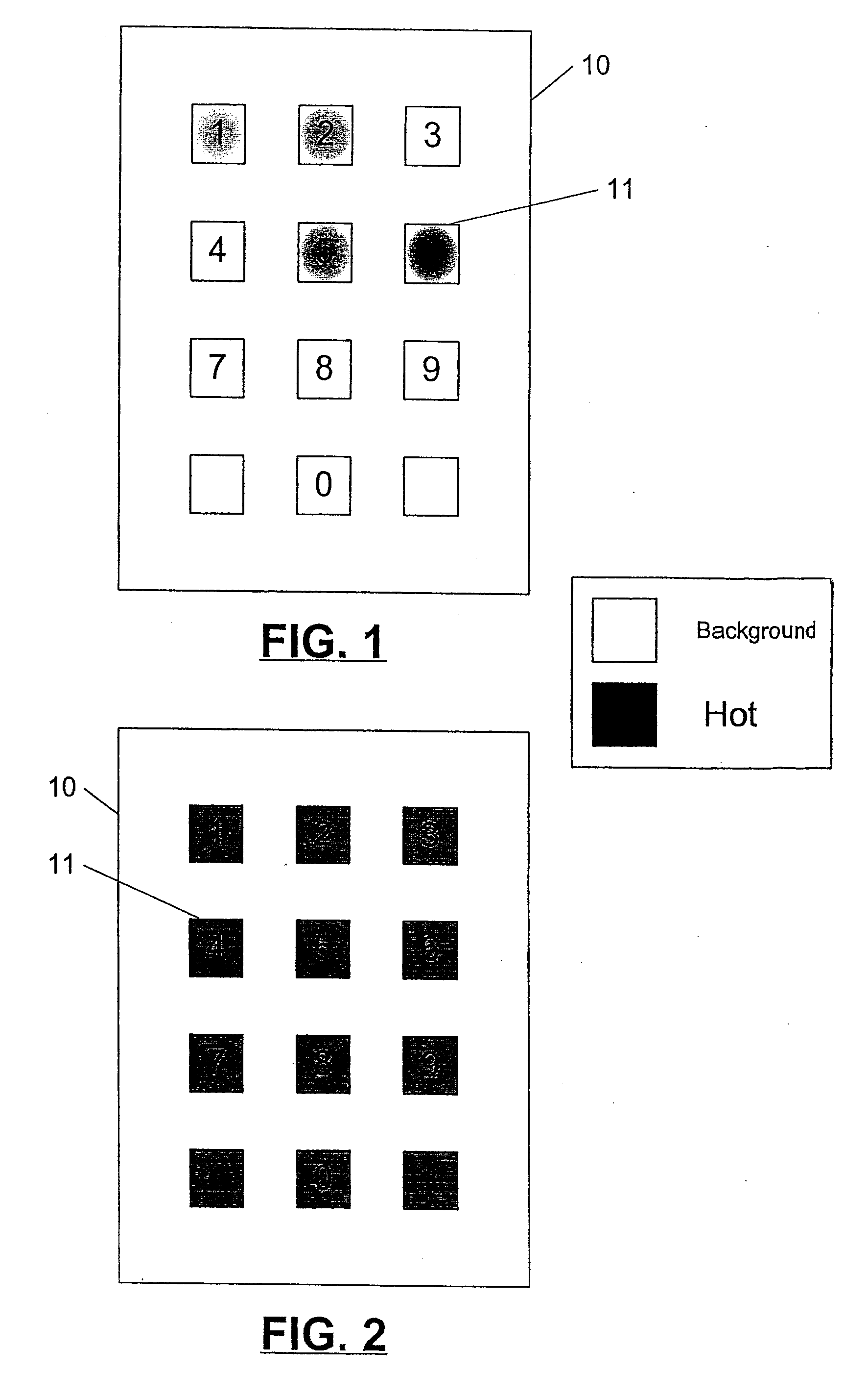
[0034]FIG. 2 shows a data entry device 10 that utilizes keys 11 for data entry. In FIG. 2, the assumption has been made that background temperature is less than the temperature of the user. The keys 11 have been heated above background temperature so as to mask any temperature differential that might be created in the keys 11 when a user utilizes them to enter data into the data entry device 10. This masking reduces the infrared detectability of the data entered into the data entry device 10. Of course if the background temperature were hotter than the temperature of the user, the keys 11 could be cooled to mask any temperature differential that might be created in the keys 11 when the user enters data into the data entry device 10. Various systems for masking temperature differentials in data entry devices to reduce infrared detectability are described in FIGS. 3-6.
[0035] Referring now to FIG. 3, a feedback control circuit of the present invention will now be described. A temperature sensor 30 is operably associated with a data entry device 10. The temperature sensor 30 measures the temperature of the external surface of the data entry device 10. The temperature sensor 30 is also operably associated with a control circuit 31, which is operably associated with a heating/cooling device 32. The data entry device 10 may be a keypad, a keyboard, a touch-tone phone, or any other known data entry device. The temperature sensor 30 may conveniently be a thermocouple or any other known temperature-sensing device. The heating/cooling device 32 may be a resistive heating element, an infrared emitting lamp, a blower, or any other known means for providing cooling or heating to a data entry device.
[0036] Still referring to FIG. 3, the temperature sensor 30 provides the control circuit 31 with the external temperature of the data entry device 10. The control circuit 31 compares the external temperature of the data entry device 10 as measured by the temperature sensor 30 with a predetermined setpoint. If the external temperature of the data entry device 10 as measured by the temperature sensor 30 is higher than the predetermined setpoint, the control circuit 31 sends a signal to the heating/cooling device 32 directing it to cool the data entry device 10. This cooling continues until the external temperature of the data entry device 10 as measured by the temperature sensor 30 equals the predetermined setpoint. At that time, the control circuit 31 sends a signal to the heating/cooling device 32 directing it to stop cooling the data entry device 10. Similarly, if the external temperature of the data entry device 10 as measured by the temperature sensor 30 is lower than the predetermined setpoint, the control circuit 31 sends a signal to the heating/cooling device 32 directing it to heat the data entry device 10. This heating continues until the external temperature of the data entry device 10 as measured by the temperature sensor 30 equals the predetermined setpoint. At that time, the control circuit 31 sends a signal to the heating/cooling device 32 directing it to stop heating the data entry device 10. Suitable control circuits for carrying out temperature feedback control are known to those of skill in the art and need not be described further herein.
[0037] While FIG. 3 illustrates a feedback control system, as will be appreciated by those of skill in the art, an open loop system may also be utilized. Thus, for example, a heating source may be continuously operated. Also, while the present invention is described in FIG. 3 as both heating and cooling, as will be appreciated by those of skill in the art, only one of heating or cooling may be needed. Thus, the present invention should not be construed as limited to both heating and cooling.
[0038] Referring now to FIG. 4, a system for resistively heating a data entry device 10 of the present invention so as to reduce temperature differentials left in the data entry device by the user will now be described. Keys 11 reside on a data entry device 10. A resistive heating element 40 also resides on the data entry device 10 such that the resistive heating element 40 provides heat to the keys 11 when an electrical current is applied to the resistive heating element. The resistive heating element 40 may conveniently be a resistive pattern of wires surrounding the keys 11. The resistive heating element 40 could also be a resistive layer formed as part of a data entry device 10, which is formed using methods such as those described in U.S. Pat. No. 5,828,016 to Grannan et al. entitled “Low Profile Tactile Switch”, the disclosure of which is incorporated herein by reference. The keys 11 could be constructed from a thermally conductive material such as aluminum, copper, nickel, or any other thermally conductive material. Alternatively, the keys 11 could be plated with a thermally conductive material such as aluminum, copper, nickel, or any other thermally conductive material.
[0039] Referring now to FIG. 5, a system for heating or cooling a data entry device 10 by convection will now be described. A blower 50 directs a stream of air 51 in close proximity to a data entry device 10. The stream of air 51 may be temperature-controlled such that it is hotter or cooler than the data entry device 10. The stream of air 51 may blow directly on the data entry device 10, thus heating or cooling the surface of the data entry device 10. Heating the device using the stream of air may reduce the temperature differentials in the data entry device created when a user enters data into the device. Alternatively, or concurrently, the stream of air 51 could be directed so as to form a thermal curtain in front of the data entry device 10. The thermal curtain could mask temperature differentials created when a user enters data into the data entry device 10 by forming a thermal barrier in front of the data entry device 10. If an eavesdropper attempted to image the data entry device 10 with an infrared-imaging device, the thermal barrier would create an image on the device that masks the image of the data entry device 10. As viewed using the infrared-imaging device, the thermal barrier may appear to be a substantially opaque curtain draped in front of the data entry device 10.
[0040] Referring now to FIG. 6, a system for heating a data entry device 10 by radiation will now be described. An infrared emitting lamp 60 is operably associated with a data entry device 10. The infrared emitting lamp 60 radiates heat 61 in proximity to the data entry device 10. The infrared emitting lamp 60 may radiate directly onto the data entry device 10, thus heating the surface of the data entry device 10. Alternatively, or concurrently, the infrared emitting lamp 60 may radiate in front of the data entry device 10 forming a thermal curtain in front of the data entry device 10. As with the stream of air, the thermal curtain could mask temperature differentials created when a user enters data into the data entry device 10 by forming a thermal barrier in front of the data entry device 10. If an eavesdropper attempted to image the data entry device 10 with an infrared-imaging device, the thermal barrier would create an image on the device that masks the image of the data entry device 10. As viewed using the infrared-imaging device, the thermal barrier may appear to be a substantially opaque curtain draped in front of the data entry device 10.
[0041] The foregoing Figures and descriptions have shown how the present invention can be used to reduce temperature differentials left in a data entry device when a user enters data into the device. However, the present invention is not limited to protecting data entry to a data entry device from thermal eavesdropping. The present invention also is directed to protecting data entry to a data entry device from audio eavesdropping. Various systems for masking sound waves created by data entry into data entry devices to reduce audio detectability are described in FIGS. 7-8.
[0042] Referring now to FIG. 7, a system for canceling the sound waves produced by entering data into a data entry device 10 will be described. A sensitive microphone 70 is operably associated with a data entry device 10. The sensitive microphone 70 receives sound waves produced by the entering of data into a data entry device 10 by a user. The sensitive microphone 71, which is also operably associated with a noise cancellation circuit 71, converts the sound waves to an electrical signal and sends the electrical signal to the noise cancellation circuit 71. After receiving the electrical signal, the noise cancellation circuit 71 shifts the phase of the electrical signal, preferably by 180°. The phase-shift may be accomplished in real time using an adaptive digital signal processor such as those known to those skilled in the art. The processor delays components of the audio spectrum by one-half wavelength so that they are out of phase with the audio inputs. Then, the noise cancellation circuit 71 sends the phase-shifted electrical signal to a speaker 72. The speaker 72 is located in close proximity to the data entry device 10. The speaker 72 converts the phase-shifted electrical signal to an audio signal. The speaker then emits sound waves 73 corresponding to the audio signal. The emitted sound waves 73 may be substantially 180° out of phase with the sound waves produced by the entry of data into the data entry device 10 by a user. Thus, the emitted sound waves 73 may substantially cancel the produced sound waves such that the operation of the keys on the data entry device may be undetectable by a listening device or have insufficient level to be differentiated from each other or background noise.
[0043] Referring now to FIG. 8, a system for providing an interfering sound pattern using a sound generator will be described. A sound generator 80 is operably associated with a speaker 81, which is operably associated with a data entry device 10. In a preferred embodiment, the sound generator 80 generates an electrical signal corresponding to pre-recorded sounds. The pre-recorded sounds are recorded sounds of random input to the data entry device 10. The sound generator 80 sends the electrical signal to the speaker 81. The speaker 81 converts the electrical signal to an audio signal and emits sound waves 82 corresponding to the audio signal in proximity to the data entry device 10. By generating an interfering sound pattern, the operation of the keys on the data entry device may be undetectable by a listening device or have insufficient level to be differentiated from each other or background noise.
[0044] In the drawings and specification, there have been disclosed typical preferred embodiments of the invention and, although specific terms are employed, they are used in a generic and descriptive sense only and not for purposes of limitation, the scope of the invention being set forth in the following claims.

PUM

no PUM

Description & Claims & Application Information

We can also present the details of the Description, Claims and Application information to help users get a comprehensive understanding of the technical details of the patent, such as background art, summary of invention, brief description of drawings, description of embodiments, and other original content. On the other hand, users can also determine the specific scope of protection of the technology through the list of claims; as well as understand the changes in the life cycle of the technology with the presentation of the patent timeline. Login to view more.
Why Eureka
Try Eureka