
Remote control device for a target designator from an attack module, attack module and designator implementing such device

Active Publication Date: 2009-05-07
NEXTER MUNITIONS
View PDF8 Cites 9 Cited by
  • Summary
  • Abstract
  • Description
  • Claims
  • Application Information

AI Technical Summary

Benefits of technology

[0014]The aim of the invention is to overcome such drawbacks by proposing remote control means that enable a reduction in the time the designator remains switched on, thereby also reducing its detectability.

Problems solved by technology

Indeed, only the designated target may be destroyed by the attack module.
The main drawback to such targets designators is their lack of secrecy.
This solution, however, has the drawback of being vulnerable to scrambling.
Furthermore, given the range of common wireless emitters, there is a risk of the designator being started-up prematurely.
Lastly, because of the long emission range, it is difficult using this concept to control the exact time at which the designator is effectively switched on depending on the configurations of the terrain.

Method used


Image

  • Remote control device for a target designator from an attack module, attack module and designator implementing such device
  • Remote control device for a target designator from an attack module, attack module and designator implementing such device
  • Remote control device for a target designator from an attack module, attack module and designator implementing such device

Examples


first embodiment

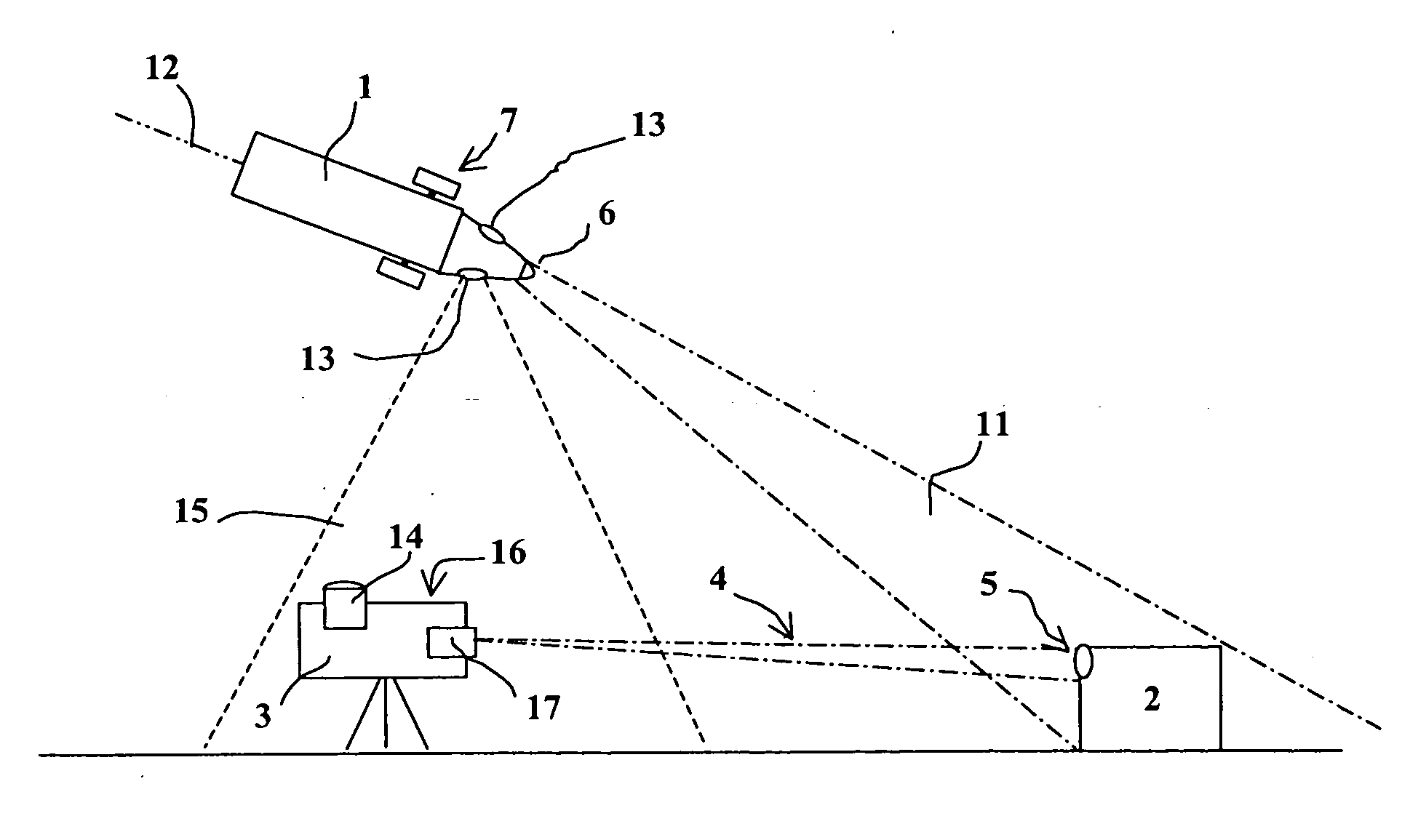
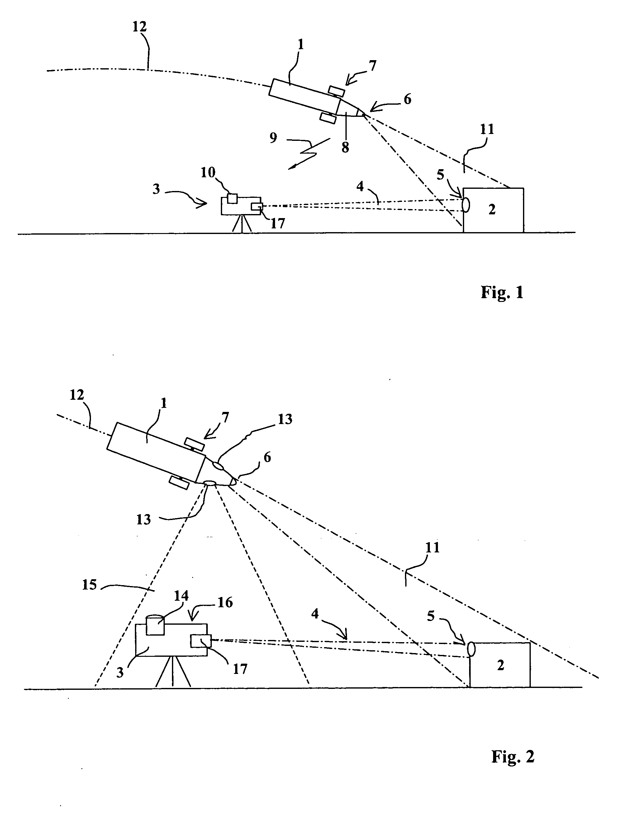
[0042]FIG. 2 shows a remote control device according to the invention.

[0043]According to this embodiment, the attack module 1 has emitter means that incorporate at least one light source 13 oriented so as to illuminate the terrain.

[0044]More specifically, the module 1 carries several light sources 13 evenly spaced angularly around the axis of the attack module. Thus, given the rotation of the module 1 around its axis, the sources 13 illuminate the ground successively one after the other.

[0045]Laser sources will preferably be used, thereby enabling the dimensions of the illumination cone 15 emitted by each source 13 to be reduced.

[0046]Furthermore, the emitter means carried by the module 1 will preferably be defined such that it ensures the emission by the light sources 13 of coded signals. It is thereby possible for a well-defined designator 3 to be controlled by a given attack module 1.

[0047]For this, each designator 3 is attributed a specific identification code and the code corre...

second embodiment

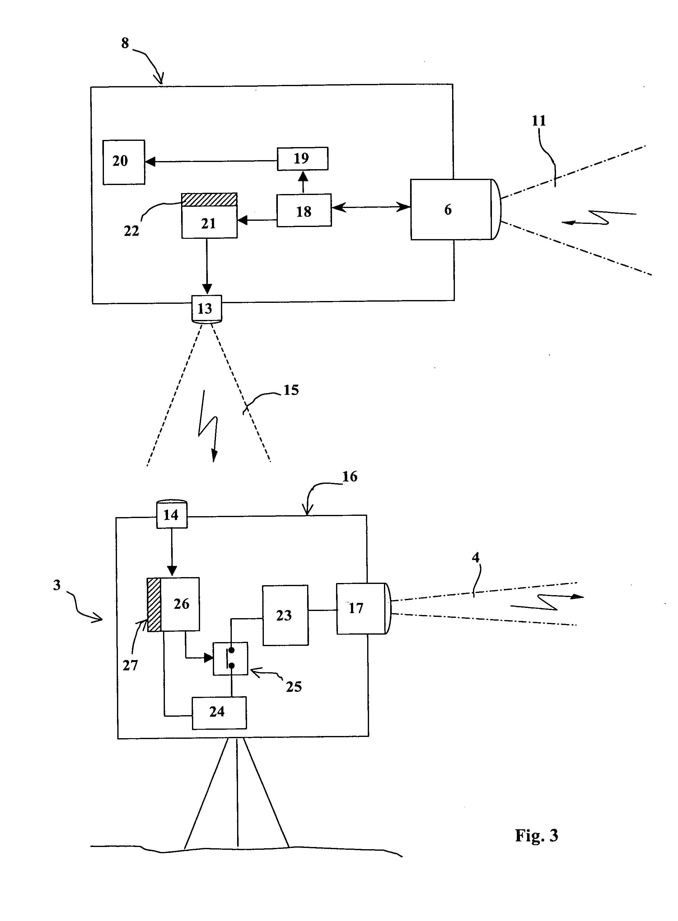
[0069]FIG. 5 shows an overview diagram of the structure of a remote control device according to the invention.

[0070]This embodiment differs from the previous one in that the unidirectional detection means 6 have been replaced by bidirectional means 31 which ensure the observation of the terrain and may also emit a coded optical signal. Means 31 may thus both act as detection means 6 and a light source 13.

[0071]This is why, on the diagram, these bidirectional optical means 31 are shown linked both to the computer 18 and to the emitter 21 (coupled with the memory 22).

[0072]In parallel, with respect to the designator 3, the emitter optics 17 will be replaced by bidirectional optics 32 able to both project a designation beam and receive the remote control signals emitted by means 31.

[0073]The bidirectional optical means 32 are thus linked both to the designation control circuit 23 and to the receiver means 26 (coupled with the memory 27).

[0074]This embodiment firstly enables the number ...


PUM


Abstract

The invention relates to a remote control device from an attack module flying over a target, module of the projectile or sub-projectile, missile or attack drone type, for a target designator positioned on a terrain of operations, comprising means to emit a remote control signal that are arranged in the attack module and at least one receiver means for the remote control signal that are integral with the designator and are associated with means to activate the start-up of the designator, wherein the emitter means incorporate at least one light source oriented so as to illuminate the terrain and in that the receiver means incorporate a detector for the radiation emitted by the light source or sources.

Description

BACKGROUND OF THE INVENTION[0001]1. Field of Invention The technical scope of the invention is that of devices to remotely control a target designator placed on a terrain of operations.[0002]2. Description of the Related Art[0003]Target designators more often than not comprise a laser source enabling a target to be optically designated.[0004]They cooperate with an attack module, such as a projectile or sub-projectile, module that is equipped with optical means enabling the designation beam to be detected after being reflected off a target.[0005]For the purposes of the invention, by attack module we mean a piece of ammunition flying over a target which it is intended to neutralize, for example a projectile, a sub-projectile, a missile or an attack drone. Attack drones are small remote-controlled aircraft (mini planes or mini helicopters). As for all ammunition, these drones are equipped with warheads or other means to neutralize a target.[0006]Depending on the technology of the attac...

Claims


Application Information

Patent Timeline
IPC IPC(8): F42B15/01G08C19/12
CPCF41G3/145F41G7/2293F41G7/226
Inventor HURTY, MICHEL JEAN
Owner NEXTER MUNITIONS
Learn More