Locking coupler for floor maintenance pad

a technology for locking couplers and floor maintenance, which is applied in the direction of carpet cleaners, instruments, photosensible materials, etc., can solve the problems of inability to provide reliable coupling and difficulty in releasing the retainer from the base, so as to achieve easy separation, easy removal, and easy movement

Inactive Publication Date: 2008-03-27
MALISH THE
View PDF29 Cites 9 Cited by
  • Summary
  • Abstract
  • Description
  • Claims
  • Application Information

AI Technical Summary

Benefits of technology

[0016]The disclosed coupling device is easily separated when a floor maintenance pad, etc. needs to be replaced. In addition, the elimination of the central post of the prior art, opens up the central portion of the coupling device and allows cleaning fluids, etc. carried by the maintenance machine to be discharged onto the floor (through the coupling device) during the floor maintenance operation.
[0017]With the disclosed snap-together coupling device, machine pads can be easily removed and reinstalled onto a floor maintenance machine. To remove the retainer from the base, the legs of the spring clip are squeezed together (via the finger receiving segments) in order to move the corner segments of the sprin

Problems solved by technology

In many of the prior art devices, release of the retainer from the base in order to release the pad from the pad driver ca

Method used


Image

  • Locking coupler for floor maintenance pad
  • Locking coupler for floor maintenance pad
  • Locking coupler for floor maintenance pad

Examples


Embodiment Construction

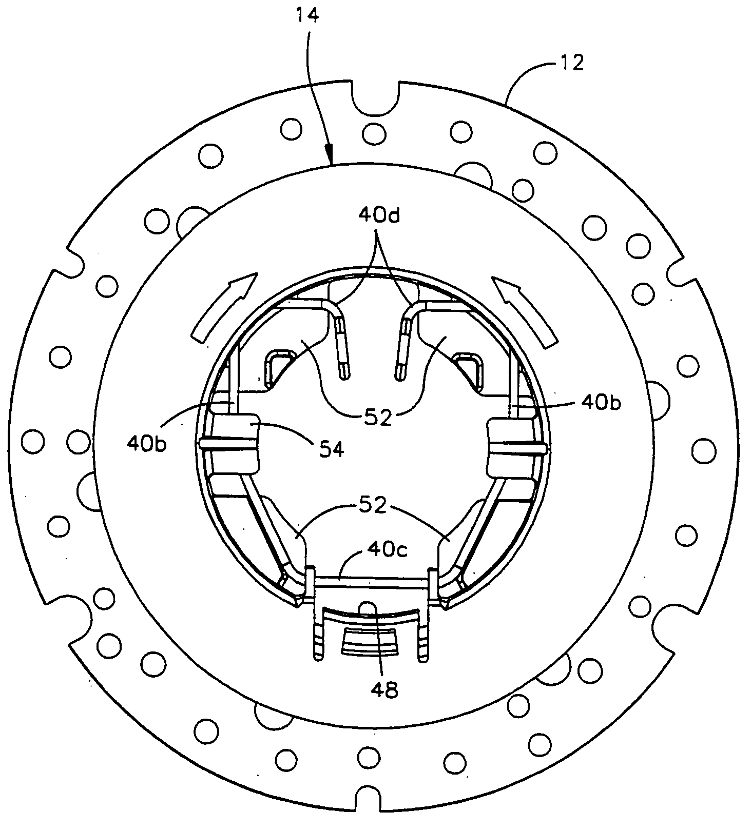
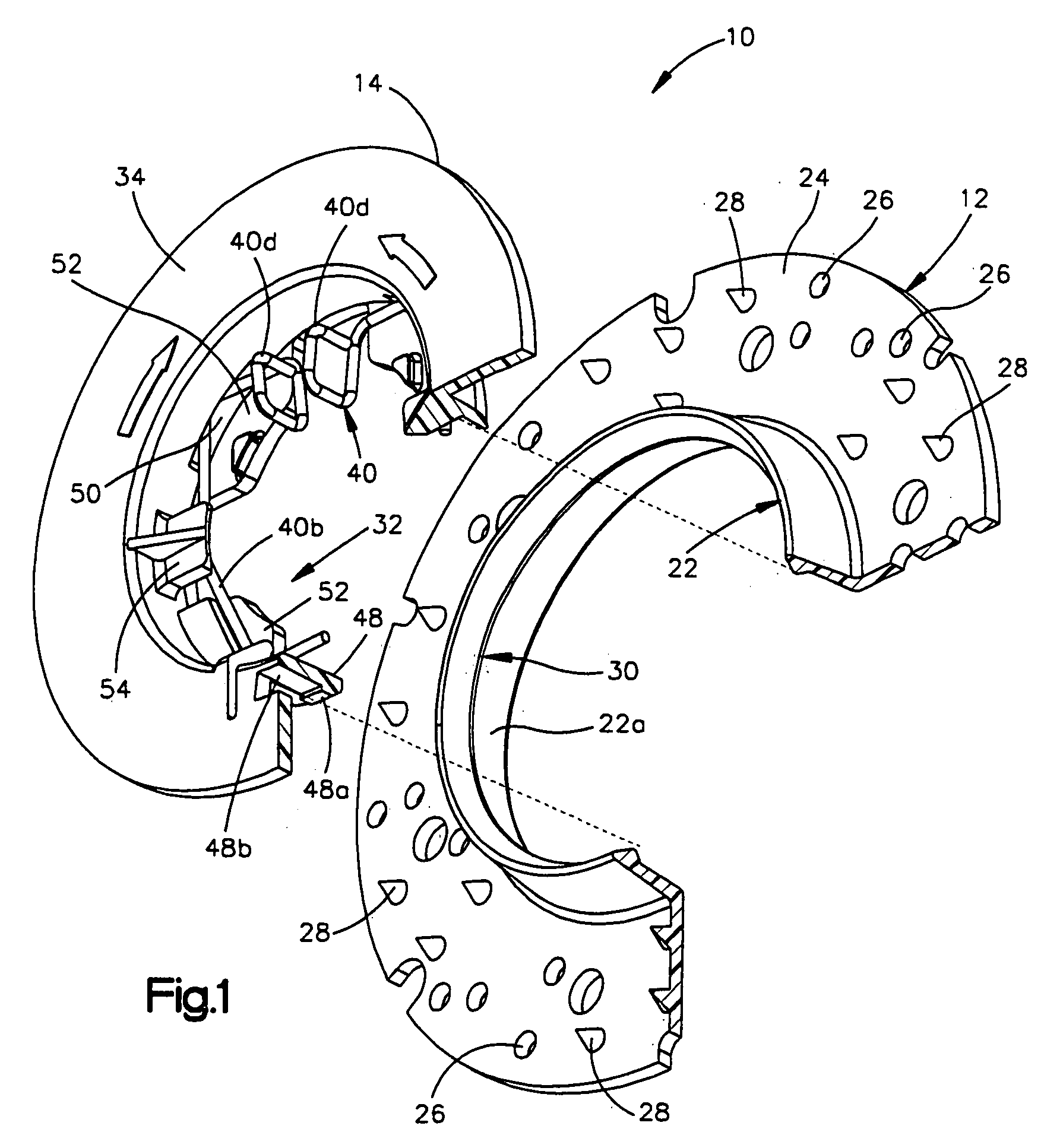
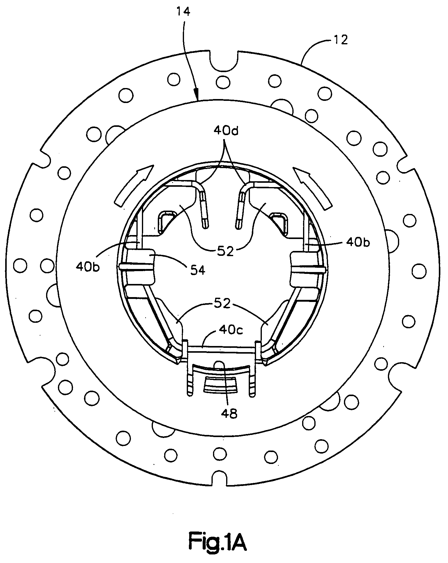
[0026]Referring to FIG. 1, a pad coupler 10 for a floor maintenance machine is shown which has a base 12 and a retainer 14. As seen in FIG. 2, the base 12 is coaxially attached to a pad driver disc 16. A portion of the retainer 14 extends through a circular mounting hole 18 of a floor maintenance pad 20 and, as will be de-scribed, “snaps” onto the base 12. The coupler 10 centers and holds the pad 20 to the disc 16 when in its coupled state.

[0027]In the machine illustrated in FIG. 2, the pad driver 16 engages the upper surface of the pad 20 with a plurality of bristles which operate to drivingly engage the pad for a variety of floor maintenance operations such as polishing, burnishing, scrubbing and stripping. Each separate task requires a pad 20 with particular abrasive characteristics. Due to the “snap together” feature of the disclosed pad coupler, the retainer 14 is readily uncoupled from the base 12 to permit an operator to replace the pad 20.

[0028]The base 12 is preferably mold...


PUM


Abstract

A coupler is disclosed for coupling floor maintenance pads to a pad driven disc. The coupler has one part which is mounted to or from an integral part of the driver disc and a second part which snaps onto the first part for holding and centering a maintenance pad to a disc. A spring lock arrangement is provided for preventing the coupler from separating and comprises a spring clip carried by the retainer engageable with lip structure formed on an axially extending wall or flange forming part of the base part. The spring clip is held to the retainer by hub segments and axially spaced tabs which define slots for slidably receiving portions of the spring clip. The spring clips include a pair of elongate legs interconnected by a bridging segment on one end and a pair of finger engageable pressure pads on opposite ends by which the spring clip is squeezed to move corner segments carried by legs inwardly in order to disengage the lip structure thereby releasing the retainer from the base.

Description

TECHNICAL FIELD OF THE INVENTION[0001]The present invention relates to apparatus for securing a pad to a rotary floor machine of the type used in floor maintenance, and more particularly, a “snap together” coupler for securing a pad to a rotating driver disc of a floor maintenance machine.BACKGROUND OF THE INVENTION[0002]Coupler devices are well known for centering and coupling a floor maintenance pad to a pad driver disc. The pad driver disc is rotated by the drive shaft of a power-driven floor maintenance machine. One example of such a coupling device is illustrated and described in U.S. Pat. No. 4,536,912.[0003]A pad coupler device typically has two parts, one of which is secured to the pad driver and the other of which is removable and is used to secure the pad to the pad driver. Various methods for maintaining the engagement between the pad driver mounted portion and the retainer portion have been suggested for use in the prior art. For example, the two parts may have threaded ...

Claims


Application Information

Patent Timeline
IPC IPC(8): A47L11/164
CPCA47L11/164A47L11/4038F16D1/116B24B45/00B24B7/186
Inventor KELLEY, PATRICK J.
Owner MALISH THE
Why Eureka
Try Eureka