Roll-up window shade with reduced-friction drive

Inactive Publication Date: 2008-03-27
BOS
View PDF3 Cites 7 Cited by
  • Summary
  • Abstract
  • Description
  • Claims
  • Application Information

AI Technical Summary

Benefits of technology

[0009] In view of the foregoing, a general object of the present invention is to provi

Problems solved by technology

Actual practice shows that with such shades, the push elements in the guide tubes consume the majority of the drive force produced by the motor.
As a result, their production and their adaptation to motor vehicle conditions are difficult.
Thus, not only is the manufacturing of the roll-up window shade cumbersome, it also is difficult to install in a motor veh

Method used


Image

  • Roll-up window shade with reduced-friction drive
  • Roll-up window shade with reduced-friction drive
  • Roll-up window shade with reduced-friction drive

Examples


Embodiment Construction

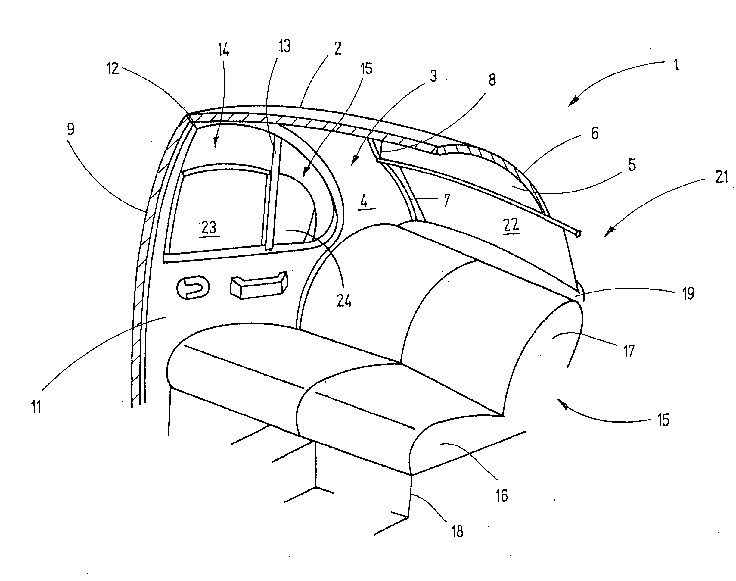
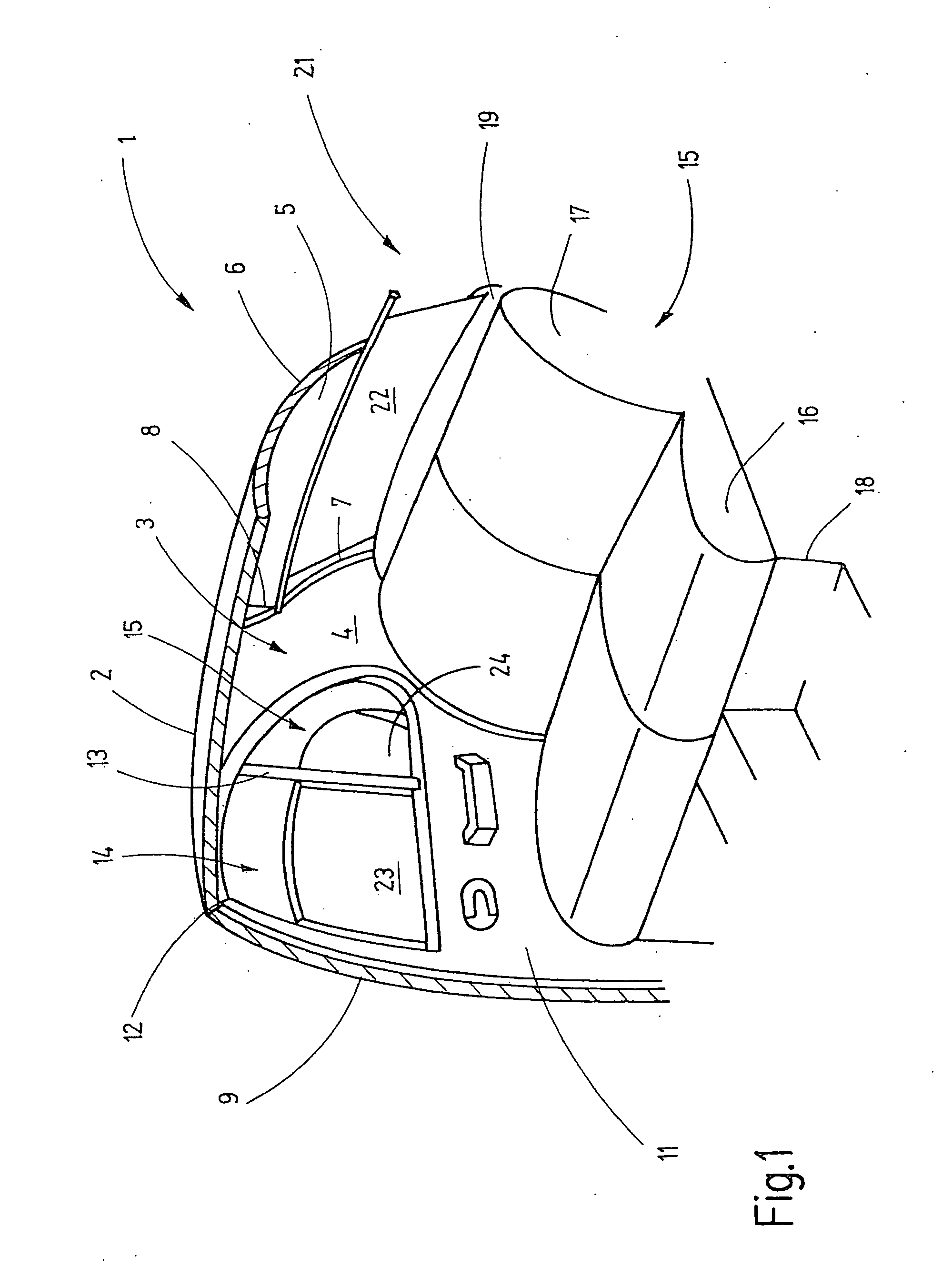
[0033] Referring to FIG. 1 of the drawings, the rear passenger compartment of a an exemplary motor vehicle is shown. The right interior side is shown in FIG. 1. The right side is the mirror image of the left interior side. Unless otherwise indicated, the explanations for the right automobile body side are also apply to the left automobile body side. The depiction in FIG. 1 is simplified; thus, for example, automobile body interior structures, such as the reinforcements, affixing elements are not shown since they are not necessary for an understanding of the invention.

[0034] The illustrated automobile body section 1 has a roof 2. A C column 3 leads downwards from a side of the roof to a car bottom assembly. A corresponding C column can also be provided on the opposite side of the motor vehicles. In this case, the interior side of the C column 3 is provided with a lining 4. A rear window 5 extends downward from the rear edge of the roof 2. The rear window 5 is bound on the upper side...


PUM


Abstract

Two drive gears are provided as an extension of the guide rails for driving a roll-up window shade for a motor vehicle. The drive gears are coupled to the winding shaft in a rotationally elastic manner. The driving is carried out via a geared motor, which acts either on the gears or on the winding shaft. The positioning of the drive gears as an extension of the guide rails avoids the guide tubes used in prior art arrangements. Thus, the friction losses found in the prior art, which consume up to 80% of the drive force, are avoided. Furthermore, manufacturing is simplified because the connection tubes having a complicated shape are not needed.

Description

FIELD OF THE INVENTION [0001] This invention relates to roll-up window shades for motor vehicles. BACKGROUND OF THE INVENTION [0002] Electrically driven rear window roll-up shades are known from the prior art. These prior art roll-up window shades have a winding shaft that is pivotably supported below the rear shelf and on which one edge of the shade is affixed. The other edge of the shade is connected to a tension rod that is guided at its end by guide rails. The guide rails are arranged next to the lateral edges of the rear window and extend from the rear shelf or below it to the vicinity of the upper edge of the window. In order to pretension the shade, there is generally a spring motor in the winding shaft or next to it. This motor biases the winding shaft in the shade wind-up direction. [0003] The unwinding or unfolding of the shade is carried out with the aid of linear push elements that run in a buckle resistant manner in the groove or slot chamber of the guide rails. A commo...

Claims


Application Information

Patent Timeline
IPC IPC(8): B60J1/20
CPCB60R5/047B60J1/2058B60J1/20B60J3/00B60J3/02
Inventor HANSEN, MELFSTARK, WOLFGANG
Owner BOS
Why Eureka
Try Eureka