Ventilation of underground porosity storage reservoirs

a porosity reservoir and underground technology, applied in drinking water installation, borehole/well accessories, constructions, etc., can solve the problems of increasing the cost and site availability of conventional open reservoirs for the storage of water, severely curtailing the flow of water downstream, and becoming prohibitively difficult to form an open reservoir in this manner

Inactive Publication Date: 2008-03-27
PS SYST
View PDF60 Cites 8 Cited by
  • Summary
  • Abstract
  • Description
  • Claims
  • Application Information

AI Technical Summary

Benefits of technology

[0012]The present invention includes an underground porosity reservoir for storing water in alluvial deposits, wherein the reservoir is formed by one or more substantially water-impermeable barriers and an aquiclude that surround a volume of alluvial materials, so that water can be stored within the spaces or pores between the alluvial materials. A conduit is positioned below a surface layer of the reservoir so that an interior volume of the conduit communicates with the alluvial deposits of the reservoir (e.g., through an opening at the end of the conduit or through a series of perforations formed along the conduit). Additionally, an air vent is provided for connecting the interior volume of the conduit with air at substantial

Problems solved by technology

It is becoming increasingly difficult, both in terms of cost and site availability, to construct conventional open reservoirs for the storage of water.
Such reservoirs typically require the construction of a dam across a river, thereby flooding vast expanses of land upstream of the dam while severely curtailing the flow of water downstream from the dam.
In light of the increasing value of water and the complexities of the various water laws across different jurisdictions, it is becoming prohibitively difficult to form an open reservoir in this manner.
A further disadvantage of open reservoirs is the high degree of evaporative losses experienced by such reservoirs due to the relatively large air/water interface.
Specifically, in arid climates (such as those found in the Western United States), open reservoirs are subject to extremely large evaporative losses.
Indeed, such evaporative losses are typically greatest where water is needed most.
Should excessive air pressure be allowed to build up in the alluvial mater

Method used


Image

  • Ventilation of underground porosity storage reservoirs
  • Ventilation of underground porosity storage reservoirs
  • Ventilation of underground porosity storage reservoirs

Examples


Embodiment Construction

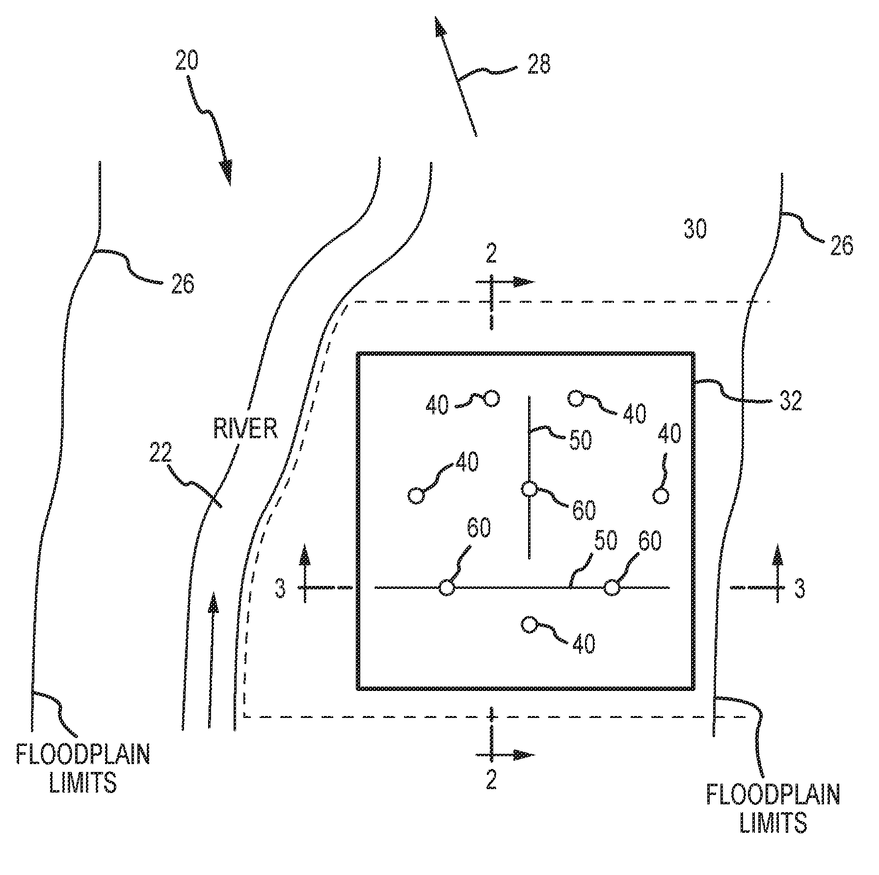
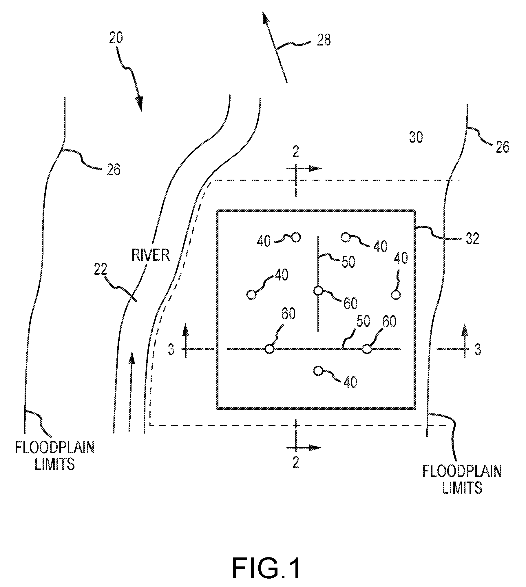
[0019]FIG. 1 illustrates an exemplary underground reservoir system in accordance with the present invention. In particular, FIG. 1 illustrates a plan view of an exemplary river system or basin 20 comprising a riverbed 22 that flows along the top of alluvial deposits 24 (FIG. 2) formed within the boundary 26 of a floodplain that extends to either side of the current riverbed 22. An arrow 28 in FIG. 1 illustrates a direction of flow of the groundwater through the alluvial deposits 24. An underground porosity storage reservoir 30 is typically formed with a regular geometric boundary 32. FIG. 1 further illustrates the position of a plurality of extraction / recharge wells 40, air ventilation conduits 50, and air vents 60 within the porosity reservoir 30, as described in greater detail below. Additional details regarding the design, construction and technical aspects of underground reservoirs are disclosed within U.S. Pat. No. 6,840,710, incorporated by reference above.

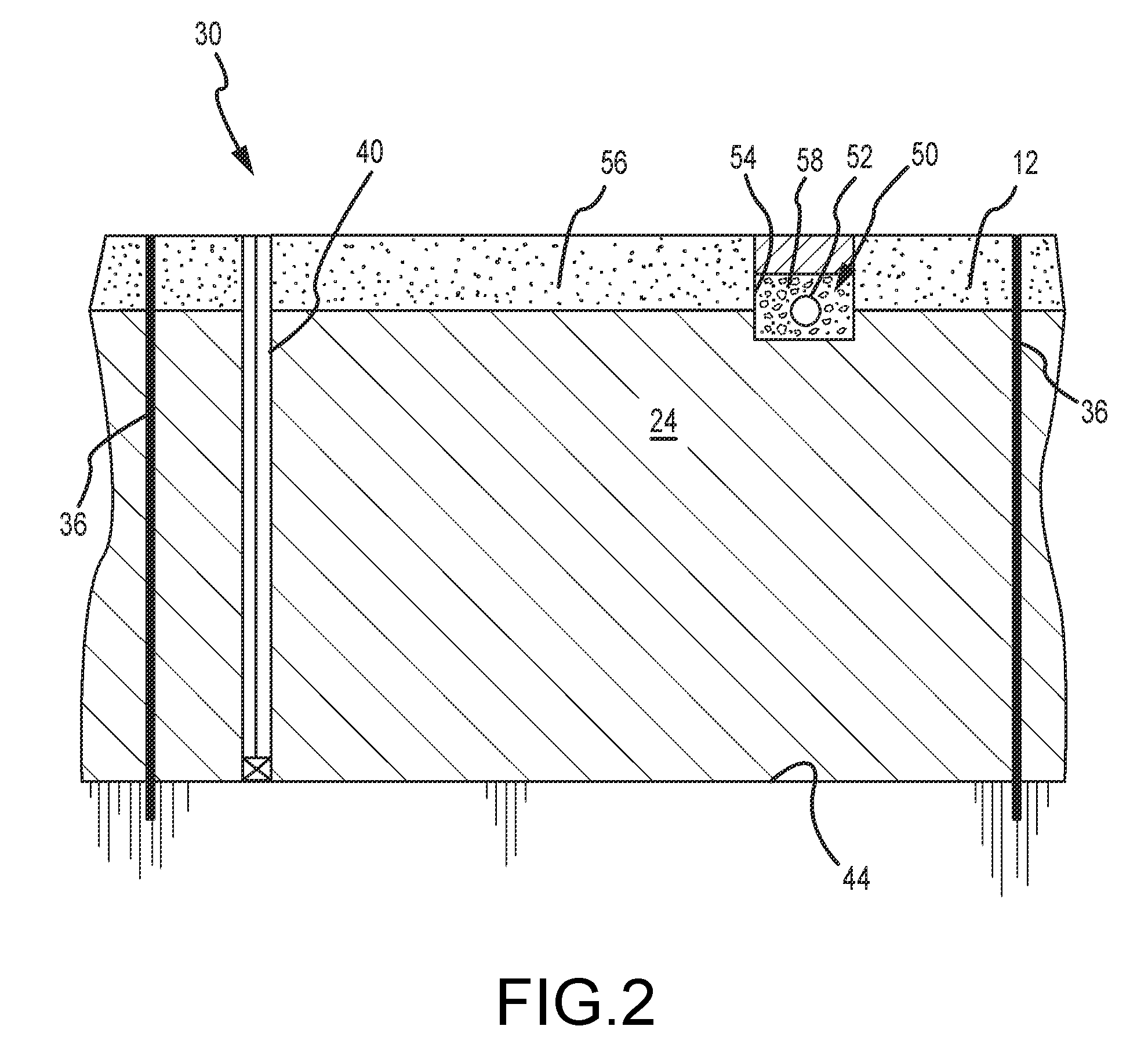
[0020]FIG. 2 provide...


PUM


Abstract

An underground porosity reservoir includes substantially impermeable barriers and an aquiclude surrounding a volume of alluvial deposits for storing water within the pore spaces of the alluvial deposits. A conduit positioned below a surface layer of the reservoir includes an interior volume that communicates with the pore spaces of the alluvial deposits. An air vent connects the interior volume of the conduit with atmospheric air above the reservoir and allows air to pass to and from the pore spaces of the reservoir. Ventilation of the porosity reservoir provides pressure-relief during reservoir filling operations (when the incoming water would otherwise cause an increase in air pressure within the reservoir), and further provides a vacuum-break as water is extracted from the reservoir (i.e., air from the conduit enters the pore spaces as the water is extracted).

Description

RELATED APPLICATIONS[0001]This application claims priority from U.S. Provisional Application No. 60 / 847,143, filed Sep. 26, 2006, which is hereby incorporated herein by reference.FIELD OF THE INVENTION[0002]This application relates generally to a method of ventilating an underground porosity reservoir, and more particularly to a method of providing pressure-relief as the reservoir is filled with water and a vacuum-break as water is extracted from the reservoir.BACKGROUND OF THE INVENTION[0003]It is becoming increasingly difficult, both in terms of cost and site availability, to construct conventional open reservoirs for the storage of water. Such reservoirs typically require the construction of a dam across a river, thereby flooding vast expanses of land upstream of the dam while severely curtailing the flow of water downstream from the dam. In light of the increasing value of water and the complexities of the various water laws across different jurisdictions, it is becoming prohibi...

Claims


Application Information

Patent Timeline
IPC IPC(8): E21B43/12
CPCE03B3/06E03B3/40E03B3/15
Inventor PETERS, STANLEY R.SUMMERS, DONALD O.
Owner PS SYST
Why Eureka
Try Eureka