Friction stir welding head and method for controlling a friction stir welding head

a friction stir welding and welding head technology, applied in the direction of manufacturing tools, soldering devices, auxillary welding devices, etc., can solve the problems of increased wear or failure of welding pins, lop fault, etc., and achieve the effect of high accuracy

Active Publication Date: 2008-03-27
AIRBUS OPERATIONS GMBH
View PDF3 Cites 49 Cited by
  • Summary
  • Abstract
  • Description
  • Claims
  • Application Information

AI Technical Summary

Benefits of technology

[0010]One object of the invention is to provide a welding head for friction stir welding in which it is possible to measure with high accuracy the distance between the welding pin or the welding pin tip and the workpiece rest or the backing, while avoiding measurement errors resulting from thermal expansion of the welding pin,

Problems solved by technology

If the distance is too short, this can lead to increased wear or failure of the welding pin.
This results in a so-called “lack of penetration” (LOP) fault.
However, since this measurement is carried out at a

Method used


Image

  • Friction stir welding head and method for controlling a friction stir welding head
  • Friction stir welding head and method for controlling a friction stir welding head
  • Friction stir welding head and method for controlling a friction stir welding head

Examples


Embodiment Construction

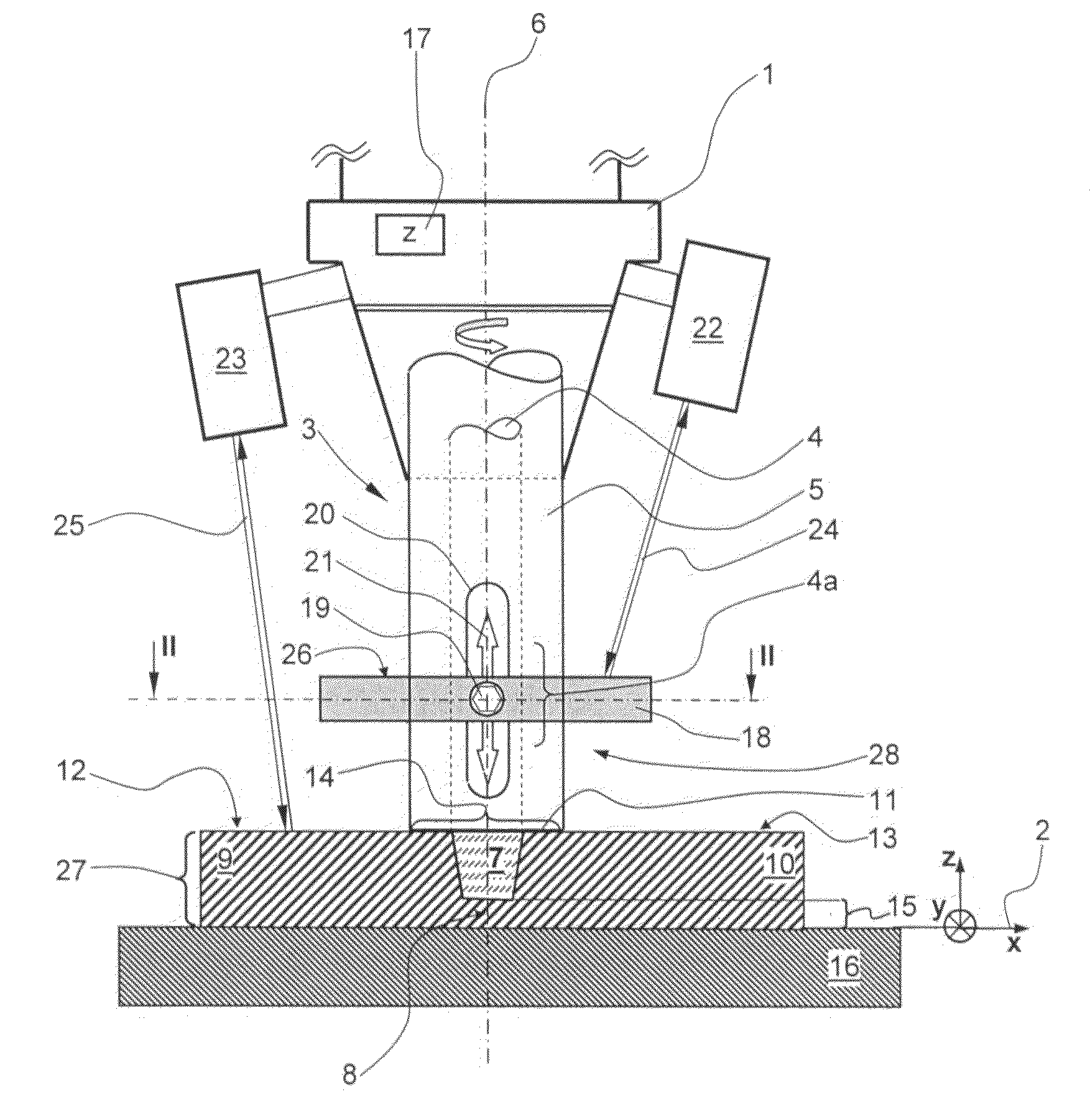
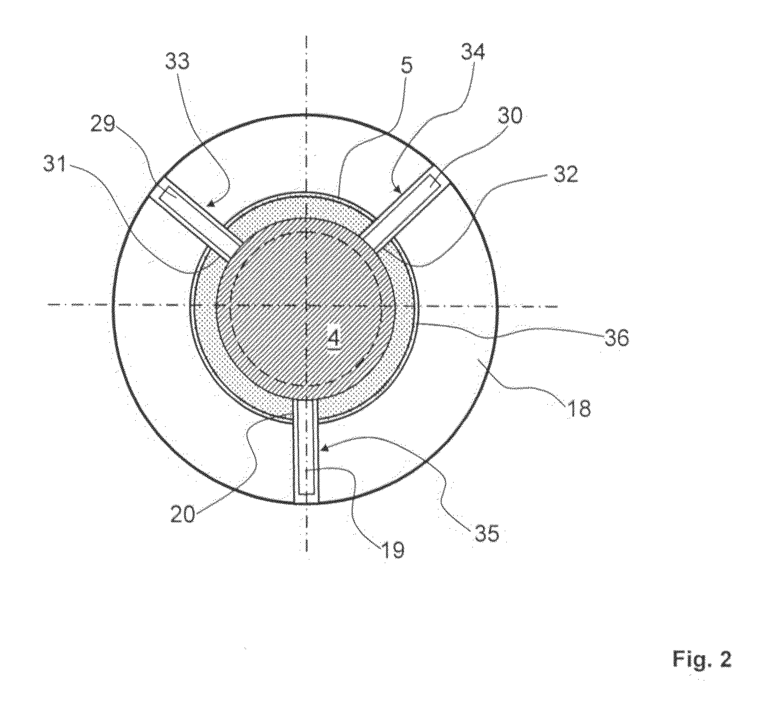
[0042]FIG. 1 shows a first embodiment variant of the friction stir welding head. A housing 1 of the friction stir welding head is arranged on a guide arrangement, which is not illustrated but for example is in the form of a CNC-controlled gantry arrangement, for free positioning in three dimensions. The friction stir welding head can in this case be positioned in the direction of the x-axis, y-axis and z-axis, which are illustrated symbolically by the coordinate system 2, with high accuracy, and with a plurality of degrees of freedom if required. The welding tool 3 is held on the housing 1 of the friction stir welding head, in a chuck, which is not shown in any more detail, or in a spindle. The chuck or the spindle, together with the welding tool, rotate at high speed with respect to the welding head, which does not rotate with them. The welding tool comprises a welding pin 4 and a shoulder tool 5, which coaxially surrounds it. The welding pin 4 has a welding pin section 4a as a mar...


PUM

PropertyMeasurementUnit
Areaaaaaaaaaaa
Distanceaaaaaaaaaa
Circumferenceaaaaaaaaaa

Abstract

The invention relates to a friction stir welding head having a housing and a welding tool with a rotating welding pin and a rotating shoulder tool for welding workpieces which rest on a workpiece rest, with the shoulder tool, which rotates in synchronism with the welding pin, coaxially surrounding the welding pin. According to the invention, a first distance between a first laser rangefinder and a welding pin section 4a can be determined by means of the first laser rangefinder. This makes it possible to determine at least one change in the distance between the welding pin tip and the workpiece rest by means of a first laser rangefinder.

Description

CROSS-REFERENCE TO RELATED APPLICATIONS[0001]This application claims the benefit of German Patent Application No. 10 2006 045 523.1 filed on Sep. 27, 2006, the entire disclosures of which are herein incorporated by reference.FIELD OF THE INVENTION[0002]The invention relates to a friction stir welding head having a housing and a welding tool with a rotating welding pin and a rotating shoulder tool for welding workpieces which rest on a workpiece rest, with the shoulder tool, which rotates in synchronism with the welding pin, coaxially surrounding the welding pin.[0003]The invention also relates to a method for open-loop control of a friction stir welding head.BACKGROUND OF THE INVENTION[0004]Friction stir welded joints which are in components have a virtually optimum joint structure in the bead formation area, which is virtually comparable to the original material characteristics of the components. The use of friction stir welding (FSW) for joining workpieces therefore makes it possi...

Claims


Application Information

Patent Timeline
IPC IPC(8): B23K20/12B23K20/26
CPCB23K20/123
Inventor OSTERSEHLTE, HARTMUT
Owner AIRBUS OPERATIONS GMBH
Why Eureka
Try Eureka