Engine bracket

Active Publication Date: 2008-03-27
NISSAN MOTOR CO LTD +1
View PDF4 Cites 12 Cited by
  • Summary
  • Abstract
  • Description
  • Claims
  • Application Information

AI Technical Summary

Benefits of technology

[0034]The engine bracket having a fixing panel portion and a main panel portion in the form of a panel can thus be provided with a reinforcing panel portion that expands perpendicularly to either the main panel port

Problems solved by technology

However, investigation by the present inventors revealed that the engine bracket with the conventional structure described in JP-A-2003-327155 does not allow the required performance to be achieved very well.
In the engine bracket disclosed in JP-A-2003-327155, however, notches are formed in the inner peripheral surface of the bolt tightening holes, which are the seating surface of the fixing bolts, and these notches inevitably reduce the area of the surface on which the tightening force of the fixing bolts may act.
Particularly, when larger sized, or greater numbers of, notches must be provided in the inner peripheral surface of the bolt tightening holes in order to more consistently ensure that the intended breakage will occur, a resulting concern is that it may become more difficult to sufficiently increase the bolt tightening force, and more difficult to ensure a high level of reliability by ensuring stable power unit support strength over a long period of time.
To effectively ensure power unit support strength and corresponding power unit support reliability, the size and number of the notches formed in the inner peripheral surface of the bolt tightening

Method used


Image

  • Engine bracket
  • Engine bracket
  • Engine bracket

Examples


second embodiment

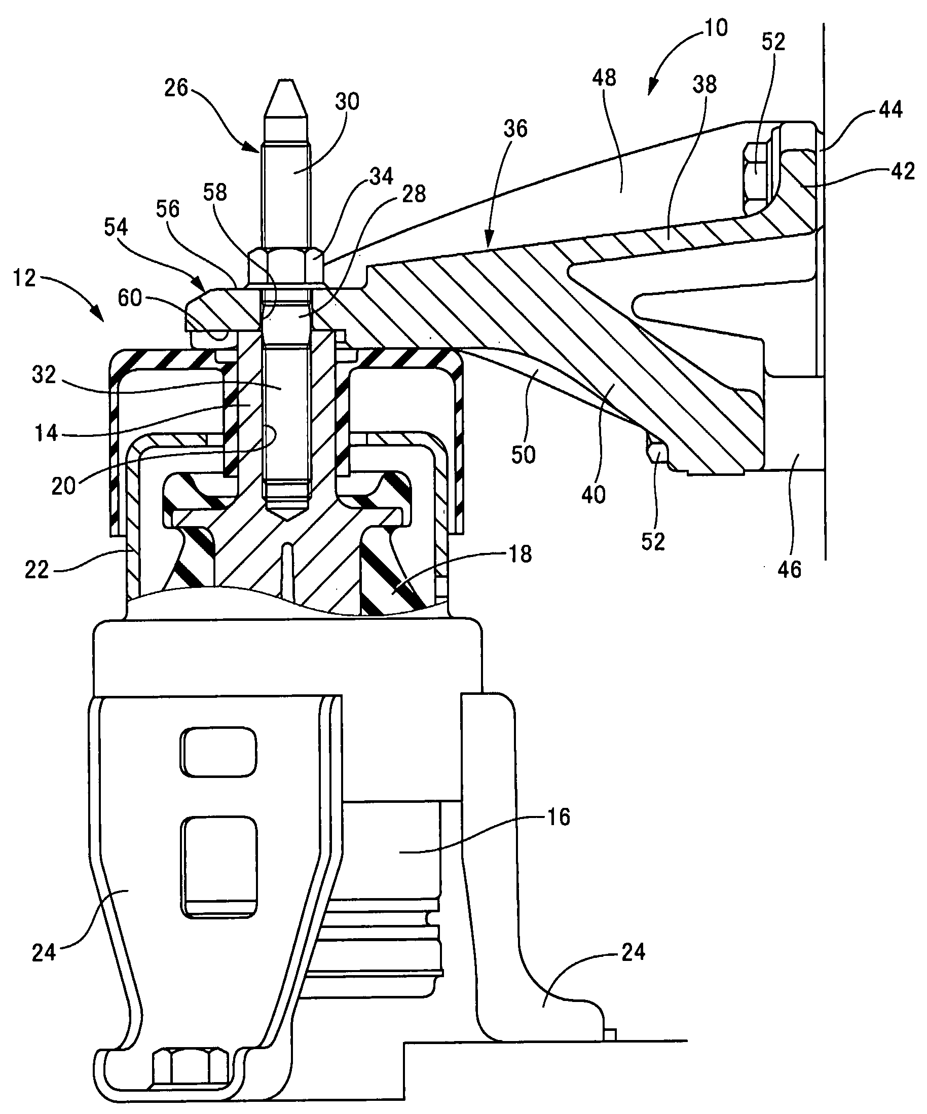
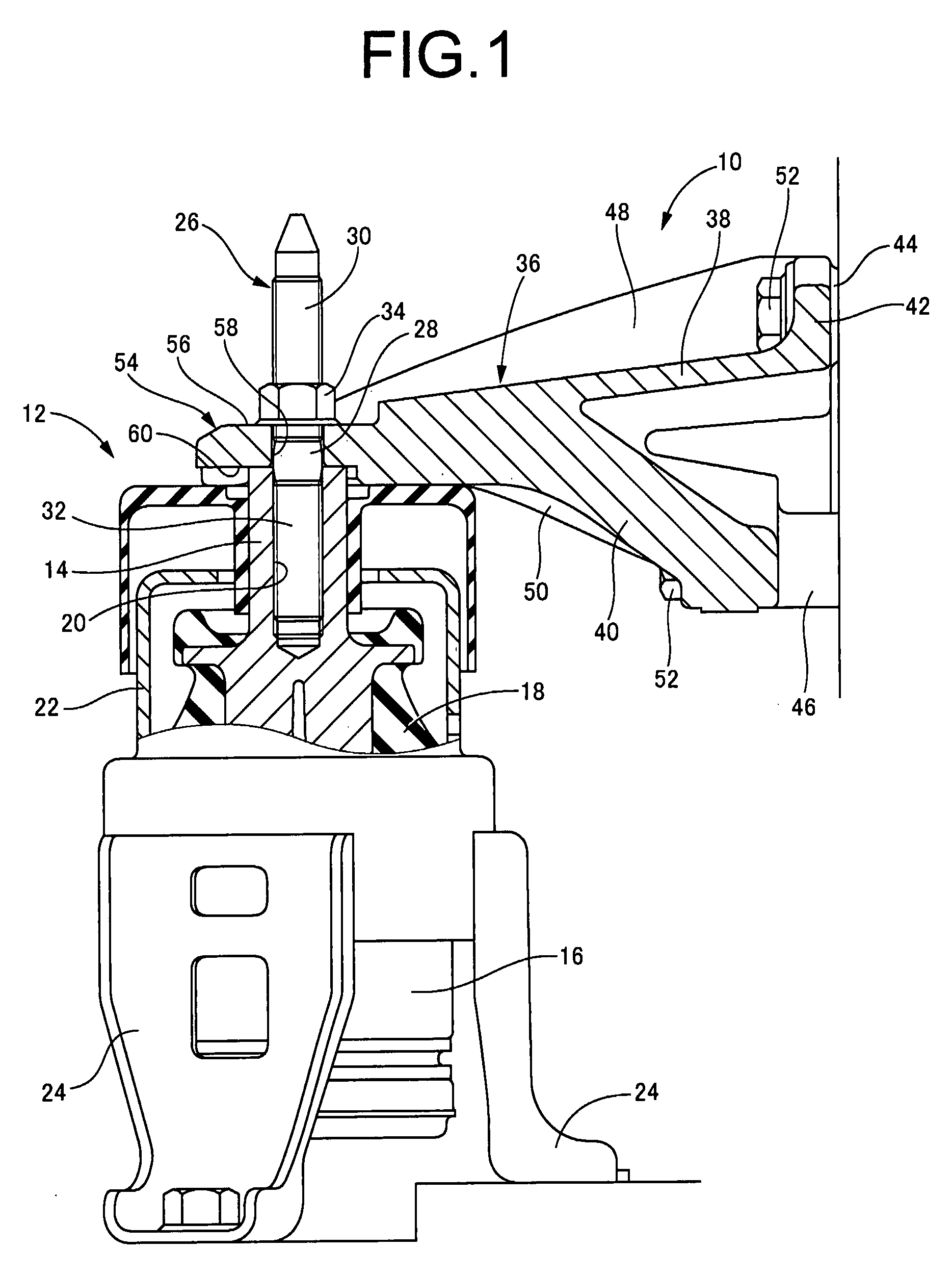
[0080]Referring next to FIG. 9, there is illustrated an automotive vehicle engine bracket 64 according to the present invention. In the following description, the same reference numerals as used in the illustrated embodiment are used for identifying structurally and functionally corresponding elements, and therefore will not be further described.

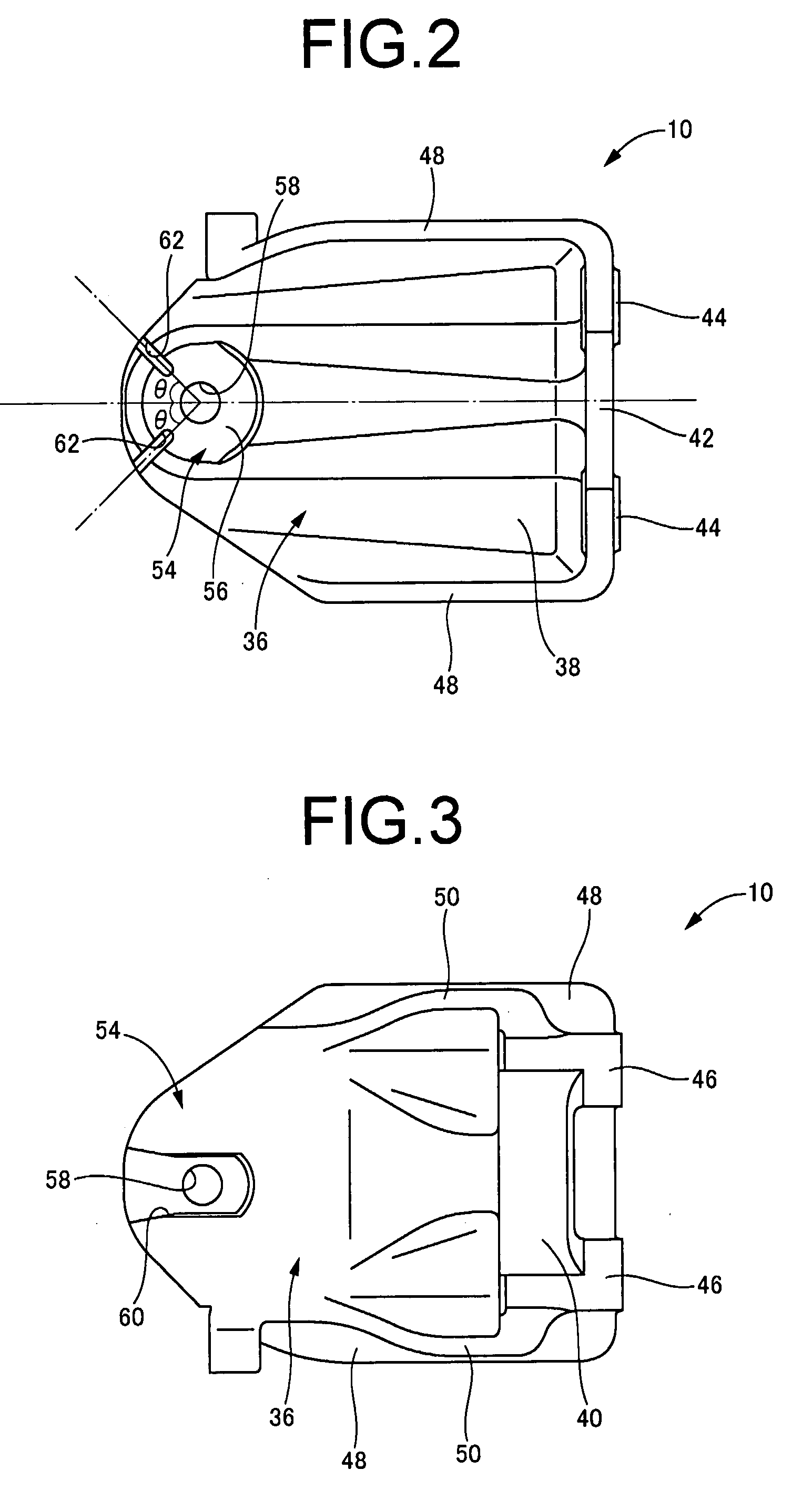
[0081]That is, in the engine bracket 64 of this embodiment, breaking guide grooves 66 are formed as the breaking grooves in the attachment panel portion 54. The breaking guide grooves 66 extend from the outer peripheral edge of the attachment panel portion 54 toward the bolt hole 58, and extend generally linearly to positions a certain distance apart on the outer periphery of the bolt hole 58.

[0082]As illustrated in FIG. 9, the breaking guide grooves 66 in this embodiment are in the form of grooves that gradually narrow from the outer peripheral edge of the attachment panel portion 54 toward the bolt hole 58 side. Although not shown in the f...

first embodiment

[0084]In the automotive vehicle engine bracket 64 constructed according to this embodiment, the surface area of the seating surface of the connecting nut 34 can be beneficially ensured so as to ensure that the engine bracket 64 is attached to the engine mount 12 during normal collision-free operation in the same manner as in the first embodiment, and the breakage of the attachment panel portion 54 by means of the breaking guide grooves 66 during collisions can prevent the power unit from intruding into the cab, ensuring better passenger safety.

[0085]The breaking guide grooves 66 in the present embodiment are also formed to a length reaching the seating surface of the connecting nut 34, thus allowing the breaking strength of the attachment panel portion 54 to be adjusted to ensure even better safety during collisions. The breaking guide grooves 66 are also formed a certain distance apart in the outer periphery of the bolt hole 58, ensuring a beneficial surface area in the seating sur...


PUM


Abstract

An engine bracket including: an attachment portion provided in a fixing location adapted to be fixed to at least one of the vehicle body and power unit; a bolt hole being formed in the attachment portion so that the attachment portion is fixed to the vehicle body or power unit by a fixing bolt inserted into the bolt hole; and at lease one breaking groove formed at an area located spaced away from the bolt hole so as to extend away from the bolt hole and toward an outer peripheral edge of the attachment portion on at least one of opposite surfaces of the attachment portion in a direction in which the fixing bolt is inserted.

Description

INCORPORATED BY REFERENCE[0001]The disclosure of Japanese Patent Application No. 2006-257723 filed on Sep. 22, 2006 including the specification, drawings and abstract is incorporated herein by reference in its entirety.BACKGROUND OF THE INVENTION[0002]1. Field of the Invention[0003]The present invention relates to an engine bracket that is used for mounting of an engine mount installed between a vehicle body and a power unit in order to join the vehicle body and power unit to each other.[0004]2. Description of the Related Art[0005]Generally, an engine mount, which is installed on a vehicle to elastically mount the power unit on the vehicle body, is attached to the power unit or the vehicle body via an engine bracket. That is, an engine bracket is used to attach an engine mount to the power unit or the vehicle body in order to deal with the various configuration of an engine mount attachment portion of such a power unit and a vehicle body.[0006]A power unit supporting structure allow...

Claims


Application Information

Patent Timeline
IPC IPC(8): B60K5/12
CPCB60K5/12
Inventor OHJI, AKIRASAIKUSA, KAZUSHI
Owner NISSAN MOTOR CO LTD
Why Eureka
Try Eureka