Clamp structure

a technology of clamping and axial rods, which is applied in the direction of clamps, manufacturing tools, and vices, etc., can solve the problems of reducing the time, inconvenient rotation of the axial rod, and taking a lot of time and effor

Inactive Publication Date: 2008-03-27
LIN TUNG CHUAN
View PDF4 Cites 35 Cited by
  • Summary
  • Abstract
  • Description
  • Claims
  • Application Information

AI Technical Summary

Benefits of technology

[0006]Therefore, it is a primary objective of the present invention to overcome the shortcomings of the prior art by providing an improved clamp structure that connects a front clamping board to a quick release unit and installs a link rod module between the front and rear clamping boards, such that after the front and rear clamping boards are driven by the quick release unit, the clamp can be opened or closed quickly.

Problems solved by technology

The aforementioned traditional clamp uses the opposite-direction screw thread sections to drive the clamp to open and close, but there are still some drawbacks in practical applications.
For example, the method of rotating the axial rod is inconvenient, which takes much time and efforts.
If an auxiliary rod (not shown in the figure) perpendicular to the axial rod is adopted to rotate the axial rod, it can reduce the time a little, but strictly speaking, such arrangement is still inconvenient.
In the method of using opposite-direction screw threads to drive the axial rod to rotate, the screw threads may be stripped by an improper use, and the rotation of the axial rod will become unsmooth, and thus the prior arts require further improvements.

Method used


Image

  • Clamp structure
  • Clamp structure
  • Clamp structure

Examples


Embodiment Construction

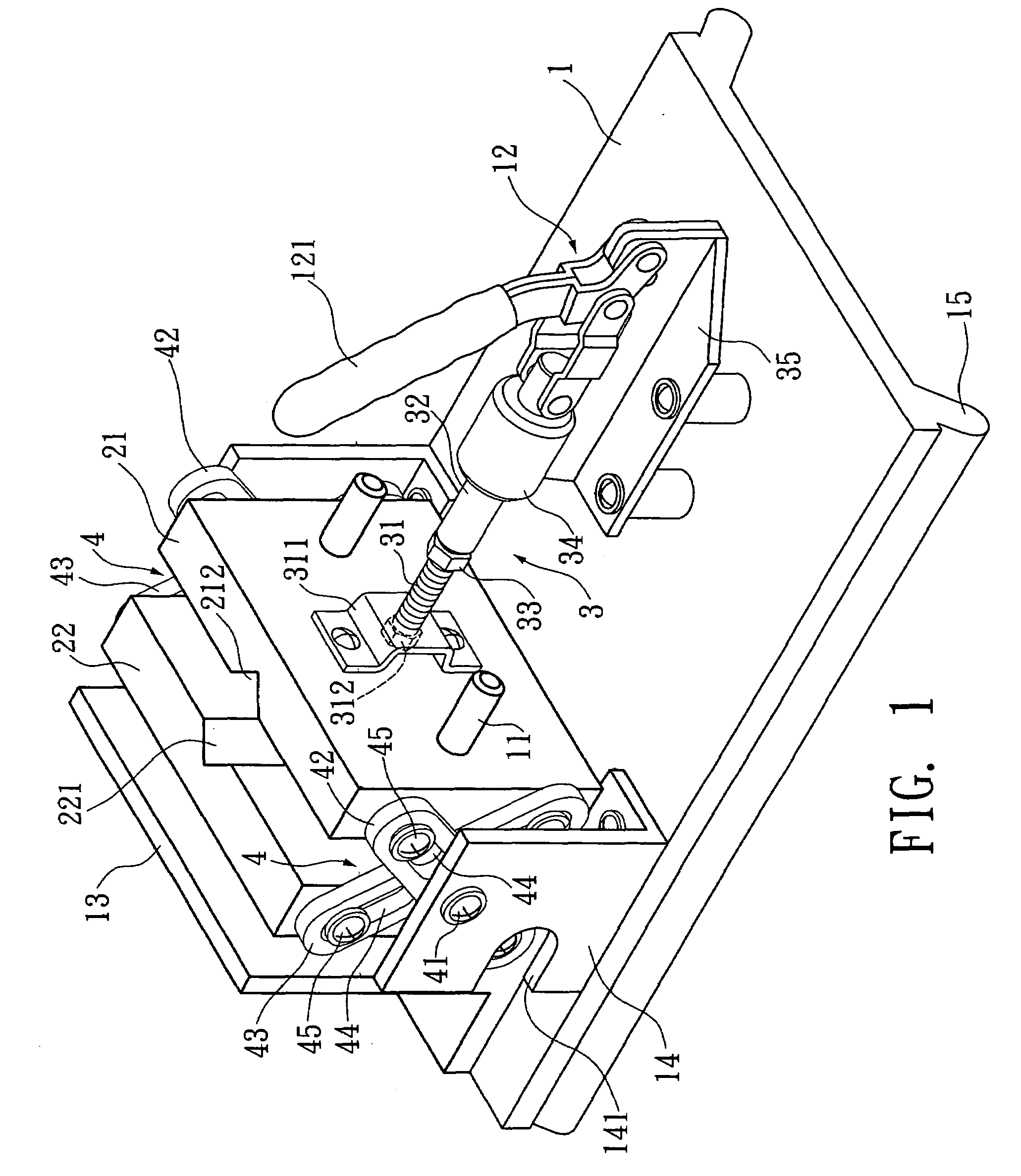
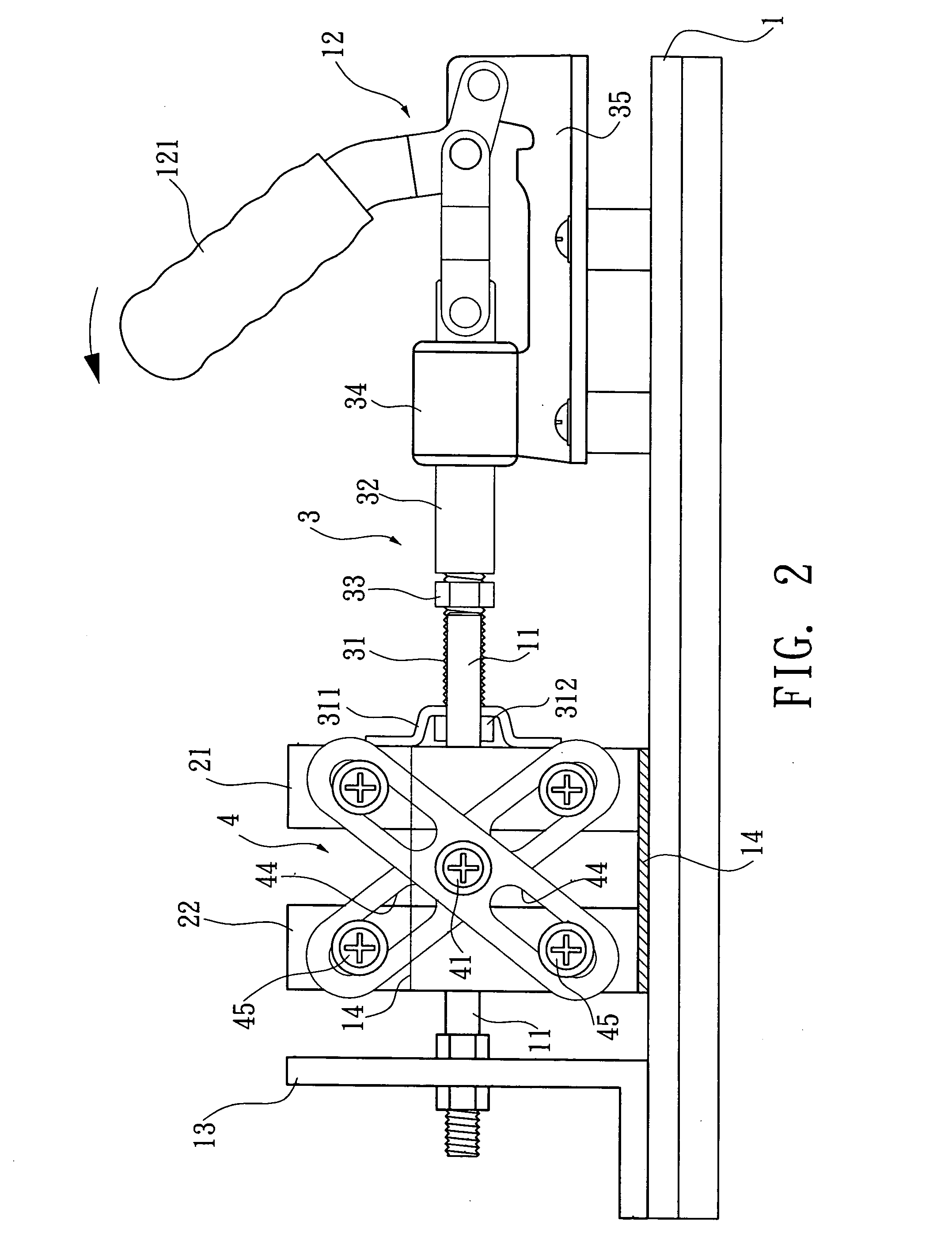
[0023]Referring to FIGS. 1 to 7, a structure in accordance to a preferred embodiment of the present invention is used for illustration, and not intended to limit the scope of patent claims of the invention.

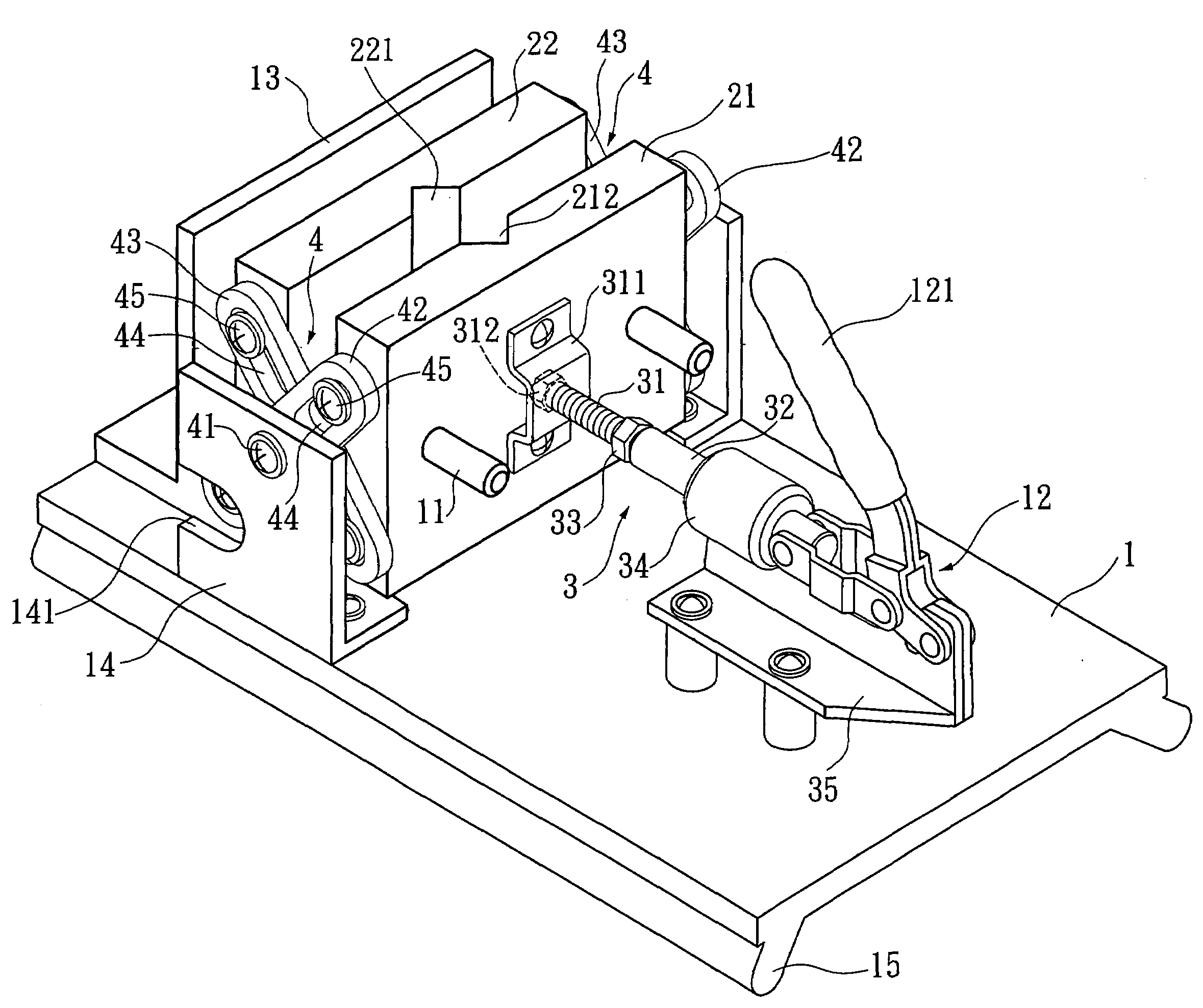
[0024]Referring to FIGS. 1 to 3 for a preferred embodiment of an improved clamp structure in accordance with the present invention, the improved clamp structure comprises a workbench 1, a front clamping board 21, a rear clamping board 22, an axial rod 3, two symmetric guiding rods 11 and two cross-shape link rod modules 4.

[0025]The workbench 1 includes a quick release unit 12 and a baffle board 13 which are disposed with a distance apart from each other and can be turned linearly, and the quick release unit 12 has a pulling portion 121, such that a force can be applied to the quick release unit 12 conveniently, and the front and rear clamping boards 21, 22 are disposed between the quick release unit 12 and the baffle board 13, and the front and rear clamping boards 21, 22 are para...


PUM


Abstract

An improved clamp structure includes a workbench, and the workbench has a quick release unit that can be turned linearly and a baffle board. A front clamping board and a rear clamping board are disposed between the quick release unit and the baffle board. An axial rod connects the front clamping board and quick release unit, and two guiding rods penetrate through the front and rear clamping boards to assist the sliding of the front and rear clamping boards. A link rod module is installed separately on the left and right walls of the front and rear clamping boards for controlling the quick release unit, such that when the axial rod drives the front clamping board to move, the front clamping board can be linked to the rear clamping board by the two link rod modules, so as to define corresponding quick opening and closing movements between the front and rear clamping boards.

Description

BACKGROUND OF THE INVENTION[0001]1. Field of the Invention[0002]The present invention relates to an improved clamp structure, and more particularly to a clamp that clamps a workpiece or places a workpiece in a position for facilitating the manufacture of the workpiece.[0003]2. Description of the Related Art[0004]Referring to FIG. 8 for a traditional clamp, the clamp includes a front clamping board 51, a rear clamping board 52, two guiding rods 53 passing between the front and rear clamping boards 51, 52 for assisting their sliding, an axial rod 54 passing through the front and rear clamping boards 51, 52, two opposite-direction screw threads 541, 542 disposed at penetrating positions of a rod body of the axial rod 54 corresponding to the front and rear clamping boards 51, 52, two opposite-direction screw threads 511, 521 disposed separately on an internal wall of a hole at a penetrating position of the front and rear clamping boards 51, 52 and passed by the axial rod 54, and a turni...

Claims


Application Information

Patent Timeline
Patent Type & Authority Applications(United States)
IPC IPC(8): B25B1/14
CPCB25B1/2405B25B1/14
Inventor LIN, TUNG-CHUAN
Owner LIN TUNG CHUAN
Why Eureka
Try Eureka