
Method Of Manufacturing Applicator For Cosmetics And Applicator Cosmetics

Inactive Publication Date: 2008-03-27
TOTO KIZAI
View PDF3 Cites 14 Cited by
  • Summary
  • Abstract
  • Description
  • Claims
  • Application Information

AI Technical Summary

Benefits of technology

[0006] According to this invention, since the mold for brush bristle has the brush grooves in the direction crossing the axial direction of the shank, the brush grooves can be formed at any position in the direction crossing the axial direction of the shank, thereby making it possible to increase degree of freedom of the arrangement of brush bristles.
[0015] The second invention is an applicator for cosmetics obtained by the aforementioned manufacturing method. In this case, it is possible to offer the same effect as that obtained by the aforementioned manufacturing method.

Problems solved by technology

However, in the conventional technique described in the above patent document, since the brush grooves are formed on the surfaces of molds for brush bristles along the axial direction of the shank, the array of brush bristles is limited to be on a substantially straight line along the axial direction of the shank, causing a problem in which arrangement of brush bristles is limited, so that there has been desired an increase in degree of freedom of the arrangement of brush bristles.

Method used


Image

  • Method Of Manufacturing Applicator For Cosmetics And Applicator Cosmetics
  • Method Of Manufacturing Applicator For Cosmetics And Applicator Cosmetics
  • Method Of Manufacturing Applicator For Cosmetics And Applicator Cosmetics

Examples


Embodiment Construction

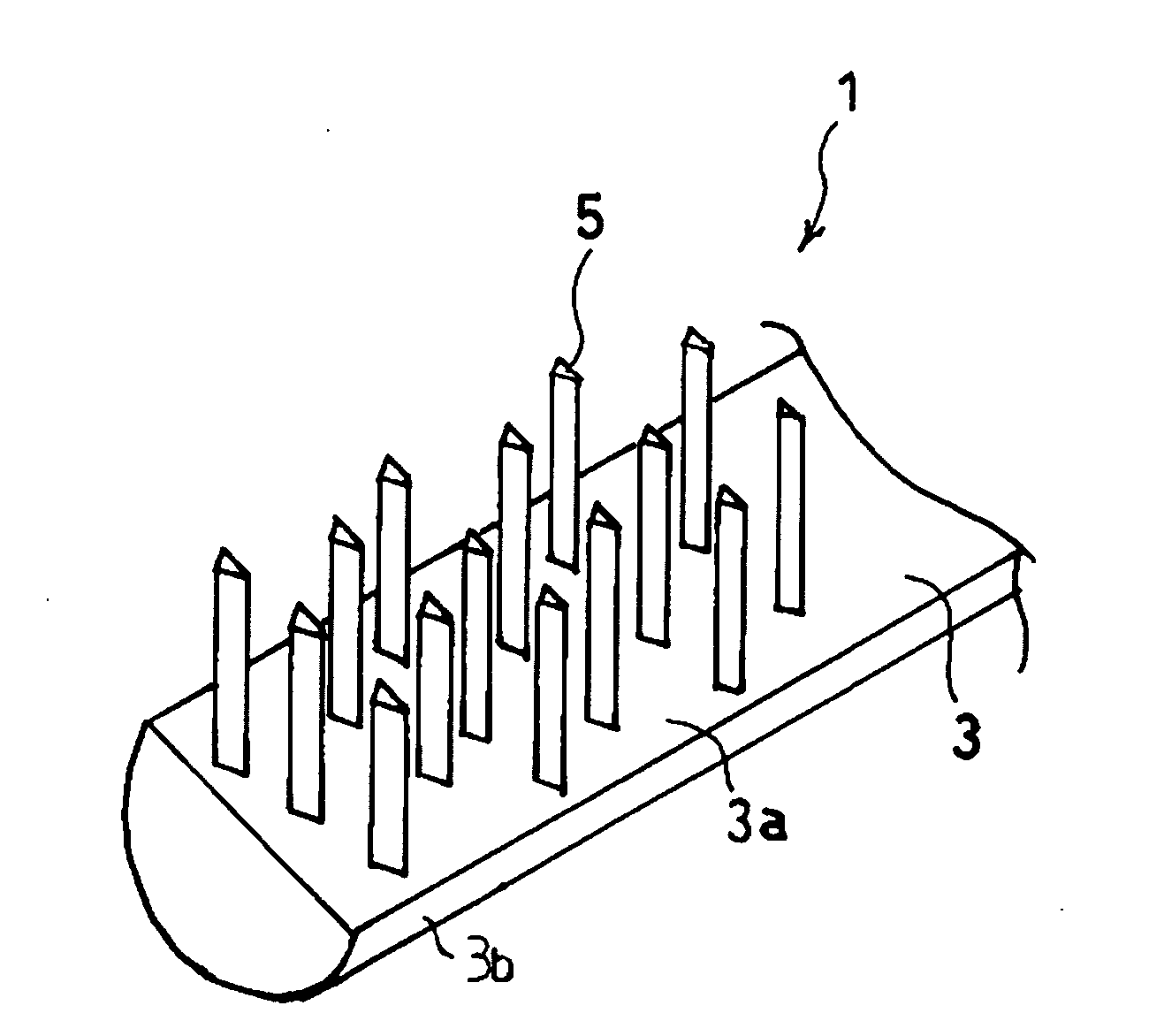
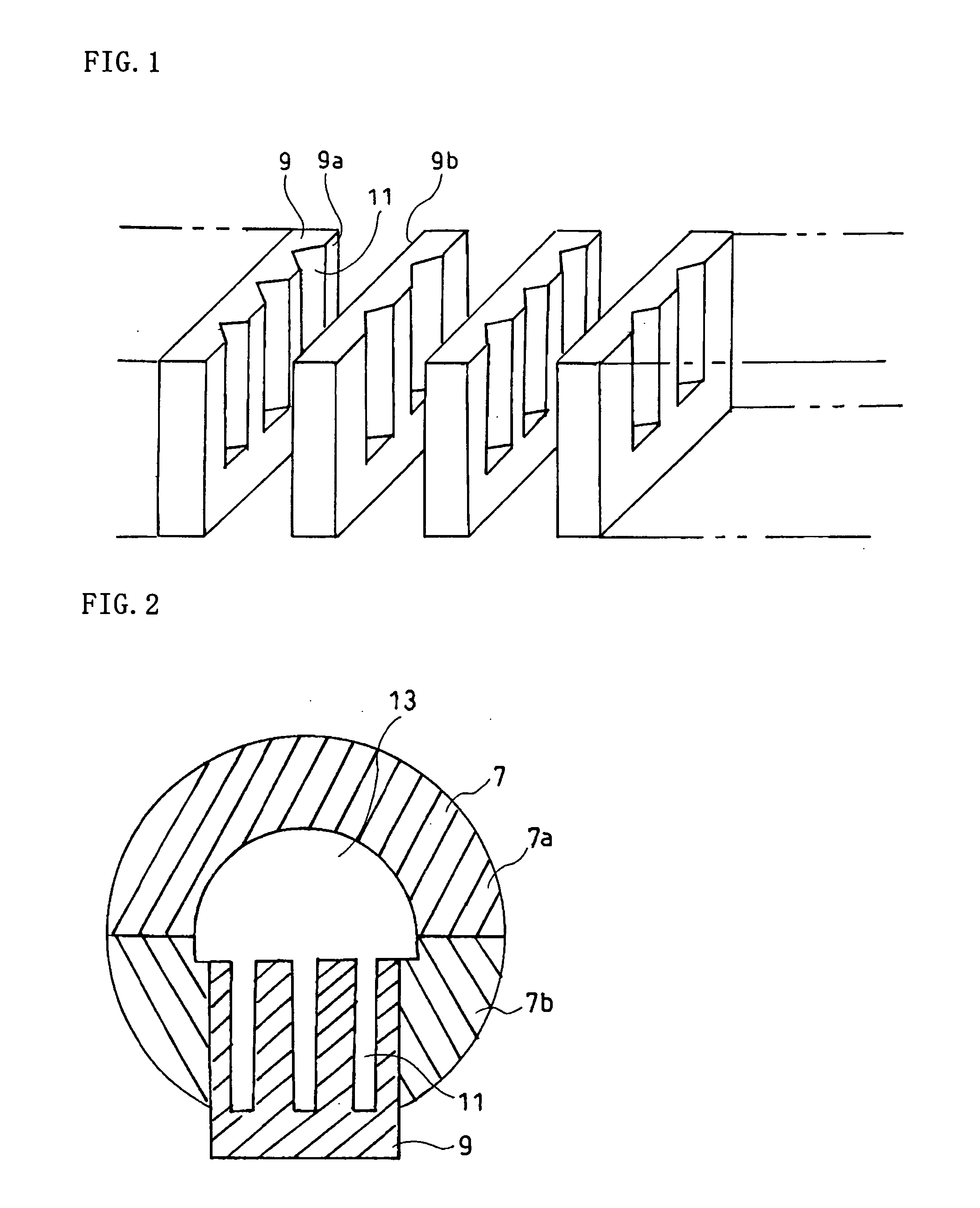
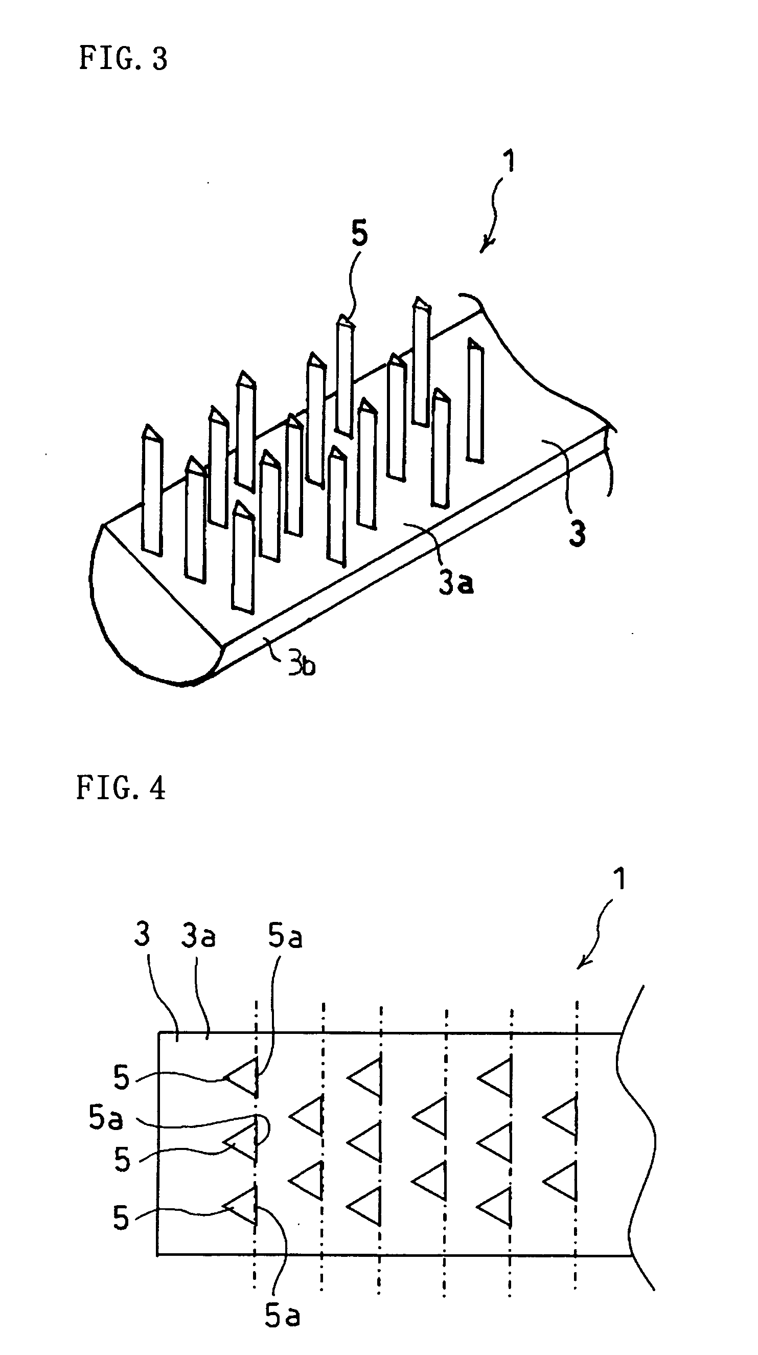
[0024] The following will specifically explain embodiments of the present invention with reference to the accompanying drawings. FIG. 1 is a perspective view illustrating essential parts of a mold for an applicator for cosmetics according to a first embodiment of the present invention; FIG. 2 is a cross-sectional view illustrating the mold for the applicator for cosmetics; FIG. 3 is a perspective view illustrating essential parts of the mold for the applicator for cosmetics according to the first embodiment of the present invention; and FIG. 4 is a plane view illustrating essential parts of the mold for the applicator for cosmetics according to the first embodiment of the present invention, respectively.

[0025] An applicator 1 for cosmetics according to an embodiment of the present invention is mainly used as a mascara brush and includes a shank 3, brush bristles 5 molded integrally with the shank 3.

[0026] The shank 3 has a flat surface 3a on which the brush bristles 5 are formed a...


PUM


Abstract

A method of manufacturing an applicator (1) for cosmetics by molding a shank (3) and a brush bristle (5) integrally with each other with a mold. The mold comprises a mold (7) for the shank and a plurality of molds (9) for brush bristle molding the brush bristle. A plurality of brush grooves (11) are formed in the surfaces of the molds for brush bristle crossing the axial direction of the shank, the molds for brush bristle are disposed adjacent to each other along the axial direction of the shank, and a resin material is filled in the mold for the shank and the molds for brush bristle for molding.

Description

TECHNICAL FIELD [0001] The present invention relates to a method for manufacturing an applicator for cosmetics and an applicator for cosmetics. BACKGROUND ART [0002] In Unexamined Japanese Patent Publication No. 2004-159823, as an applicator for cosmetics formed by molding a brush bristle and a shank integrally with each other, there is disclosed a technique in which a plurality of columns of brush bristles are formed along the axial direction of the shank. In this patent document, a plurality of brush grooves are formed on surfaces of molds for brush bristles molding the brush bristles along the axial direction of the shank. [0003] However, in the conventional technique described in the above patent document, since the brush grooves are formed on the surfaces of molds for brush bristles along the axial direction of the shank, the array of brush bristles is limited to be on a substantially straight line along the axial direction of the shank, causing a problem in which arrangement o...

Claims


Application Information

Patent Timeline
IPC IPC(8): A46D3/04A45D40/26
CPCA45D40/262A46D1/0238A46B2200/1046A46B1/00
Inventor SHIINA, HIDEKI
Owner TOTO KIZAI
Learn More