

Acoustic wave device, resonator and filter
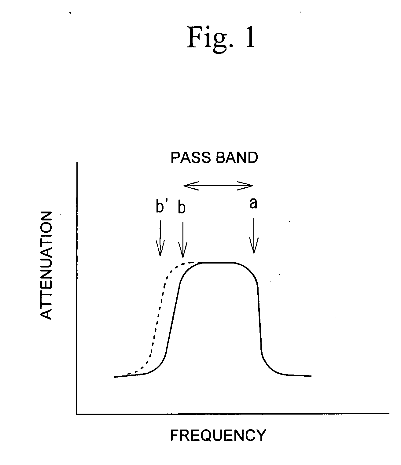
a technology of acoustic wave and a filter, applied in piezoelectric/electrostrictive/magnetostrictive devices, piezoelectric/electrostriction/magnetostriction machines, electrical apparatus, etc., can solve the problem that the shoulder b on the low-frequency side of the pass band is not improved well
- Summary
- Abstract
- Description
- Claims
- Application Information
AI Technical Summary
Benefits of technology
Problems solved by technology
Method used
Image

Examples
first embodiment
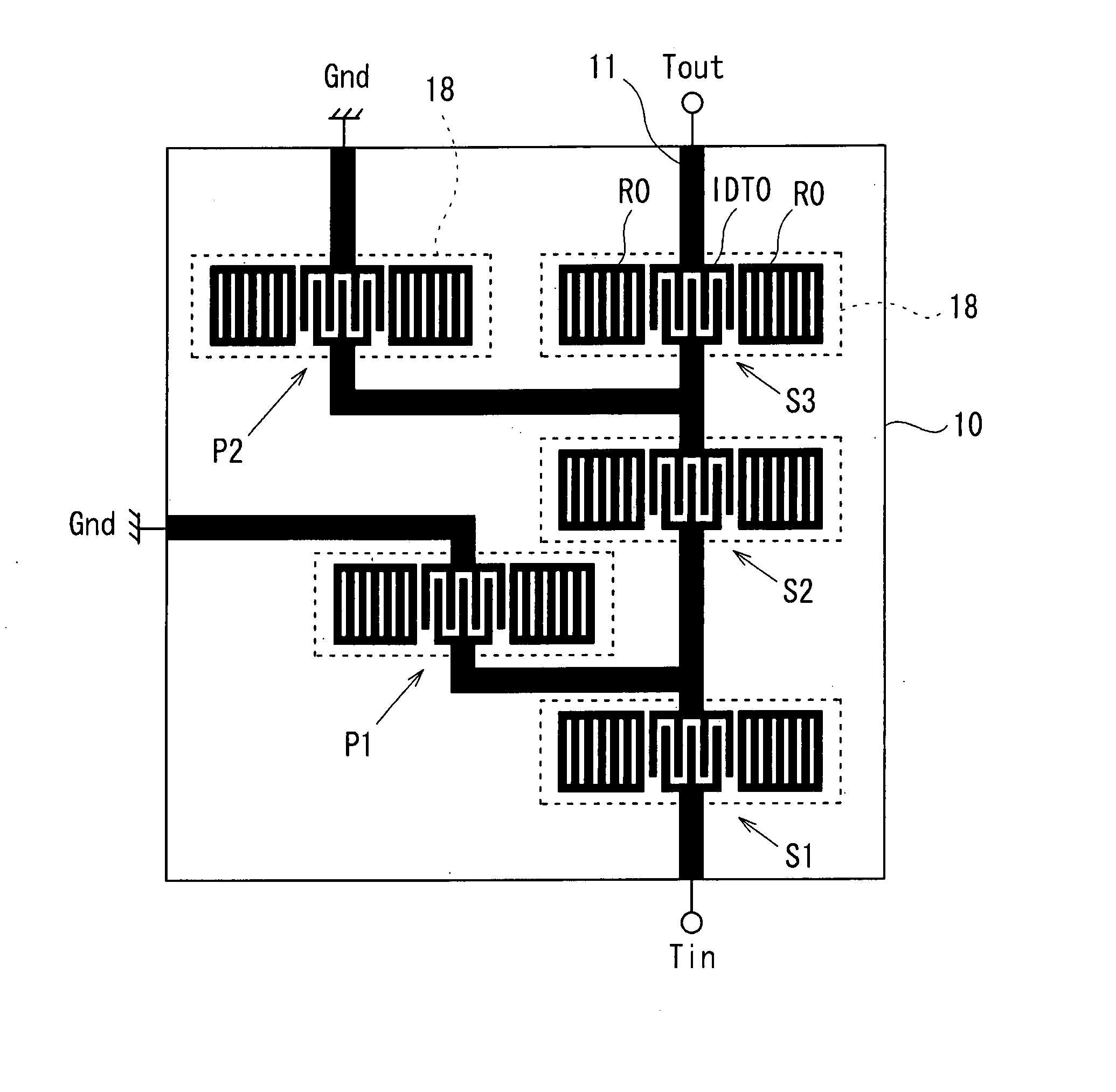
[0032] A first embodiment of the present invention is a ladder filter having a 1.9 GHz band. FIG. 4 is a schematic plan view of a ladder filter in accordance with a first comparative example. Referring to FIG. 4, solid lines indicate the electrodes 12 and interconnection lines 11 connecting the resonators formed on the piezoelectric substrate 10. Series resonators S1 through S3 are connected in series between an input terminal Tin and an output terminal Tout. A parallel resonator P1 is connected between a node connecting the series resonators S1 and S2 and ground. A parallel resonator P2 is connected between a node connecting the series resonators S2 and S3 and ground. Each of the series resonators S1 through S3 and the parallel resonators P1 and P2 is a one-port resonator. A dielectric laminate film 18 is provided to each of the series resonators S1 through S3 and the parallel resonators P1 and P2. The electrodes 12 are illustrated to see through the dielectric laminate films 18.
[...
second embodiment
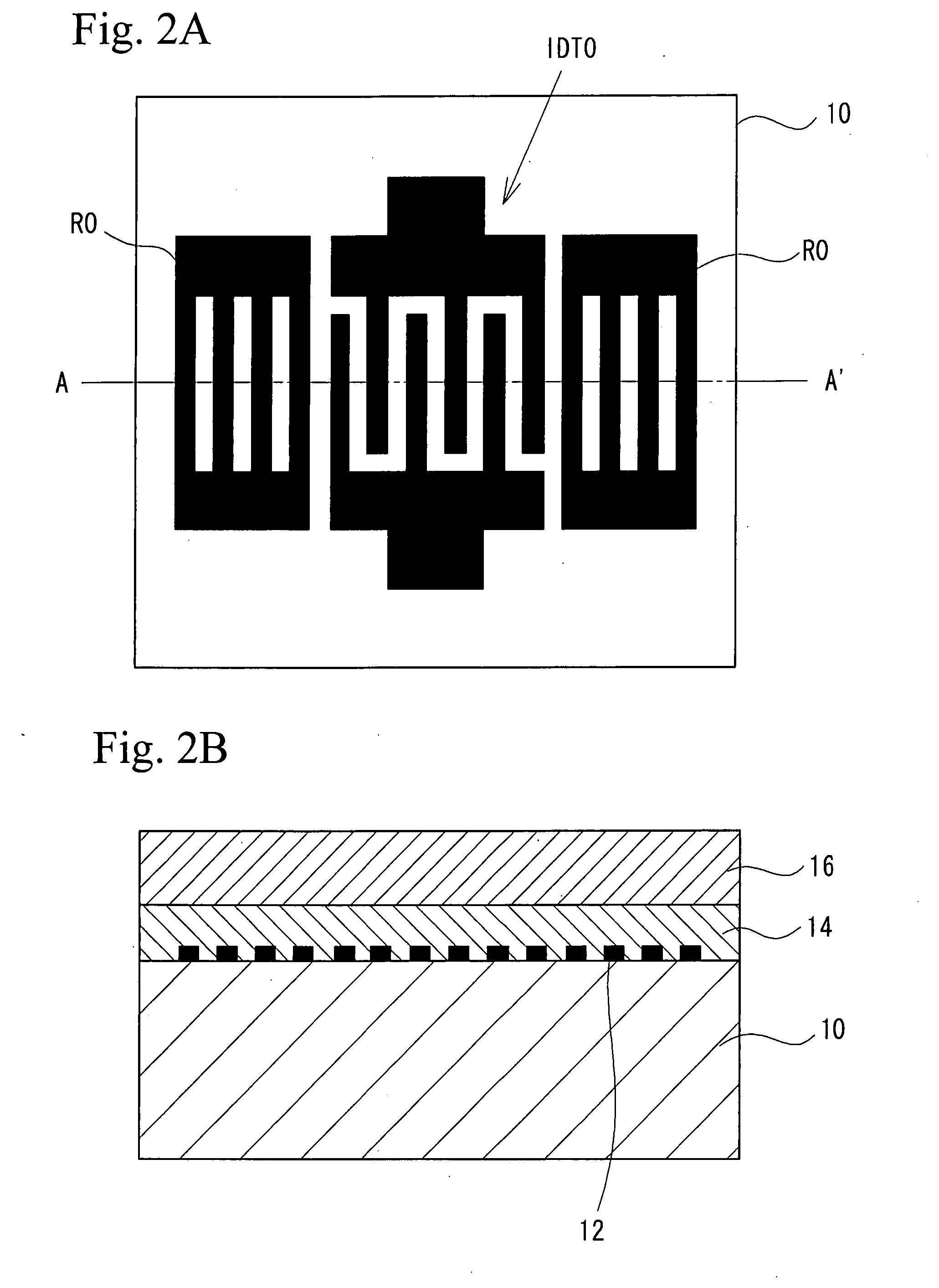
[0039] A second embodiment is a filter in which a one-port resonator and a multimode filter are connected in series. FIG. 8 is a plan view of the filter of the second embodiment. A cross section of a first acoustic wave filter F1 is the same as that of the parallel resonator of the first embodiment shown in FIG. 7, and a cross section of a second acoustic wave filter F2 is the same as that of the series resonator of the first embodiment shown in FIG. 7. Therefore, FIG. 7 will be referred to in the following description of the second embodiment. Referring to FIG. 8, the first acoustic wave filter F1 and the second acoustic wave filter F2 are connected in series between an input terminal Tin and an output terminal Tout. The first acoustic wave filter F1 is a one-port resonator having a pair IDT0 of comb electrodes and a pair of reflectors R0 arranged at both sides of IDT0. The pair IDT0 of comb electrodes is connected to the input terminal Tin and an input IDT1 of the second acoustic ...
third embodiment
[0042] A third embodiment is a filter in which multimode filters are connected in series, or are cascaded. FIG. 9 is a plan view of the filter of the third embodiment. The third embodiment has the same cross section as the second embodiment shown in FIG. 7, which will be sometimes referred to in the following description of the third embodiment. Referring to FIG. 9, a first acoustic wave filter F3 and a second acoustic wave filter F4 are connected in series between the input terminal Tin and the output terminal Tout. The first acoustic wave filter F3 is a double-mode filter having an input IDT1, two output IDT2 provided at both sides of the input IDT1, and two reflectors R1 provided further out than the two output IDT2. The input IDT1 is connected to the input terminal T1n, and the output terminal IDT2 is connected to the input IDT3 of the second acoustic wave filter F4. The first acoustic wave filter F3 is provided with the dielectric laminate film 18a composed of the first dielect...
PUM
 Abstract
Description
Claims
Application Information