Variable permeability inductor cre structures

a cre structure and variable permeability technology, applied in the direction of transformer/inductance details, inductance, electrical equipment, etc., can solve the problems of reduced effective permeability of the core, significant drawback for systems operating primarily at light load, and reduced core utilization at the light load. , to achieve the effect of increasing the utilization rate of inductor materials, reducing the effect of permeability and low permeability

Inactive Publication Date: 2008-03-27
FORD GLOBAL TECH LLC
View PDF31 Cites 17 Cited by
  • Summary
  • Abstract
  • Description
  • Claims
  • Application Information

AI Technical Summary

Benefits of technology

[0007]The embodiments of the present invention provide several advantages. One advantage provided by an embodiment of the present invention is an inductor that has at least one zone or member that has high permeability during low loading conditions and low permeability during high loading conditions. This also increases inductor material utilization for improved flux density at low current while providing desired inductance during high loading conditions without the inductor overheating.
[0009]Yet another advantage provided by another embodiment of the present invention is the ability to provide an inductor with high permeability during low loading conditions and low permeability during high loading conditions and that has controlled or limited losses, such as eddy current loss or hysteresis loss.

Problems solved by technology

The low permeability gap reduces the effective permeability of the core and thus the inductance therein.
As such, the core is not fully utilized at light load.
This is significant drawback for systems operating primarily at light load.

Method used


Image

  • Variable permeability inductor cre structures
  • Variable permeability inductor cre structures
  • Variable permeability inductor cre structures

Examples


Embodiment Construction

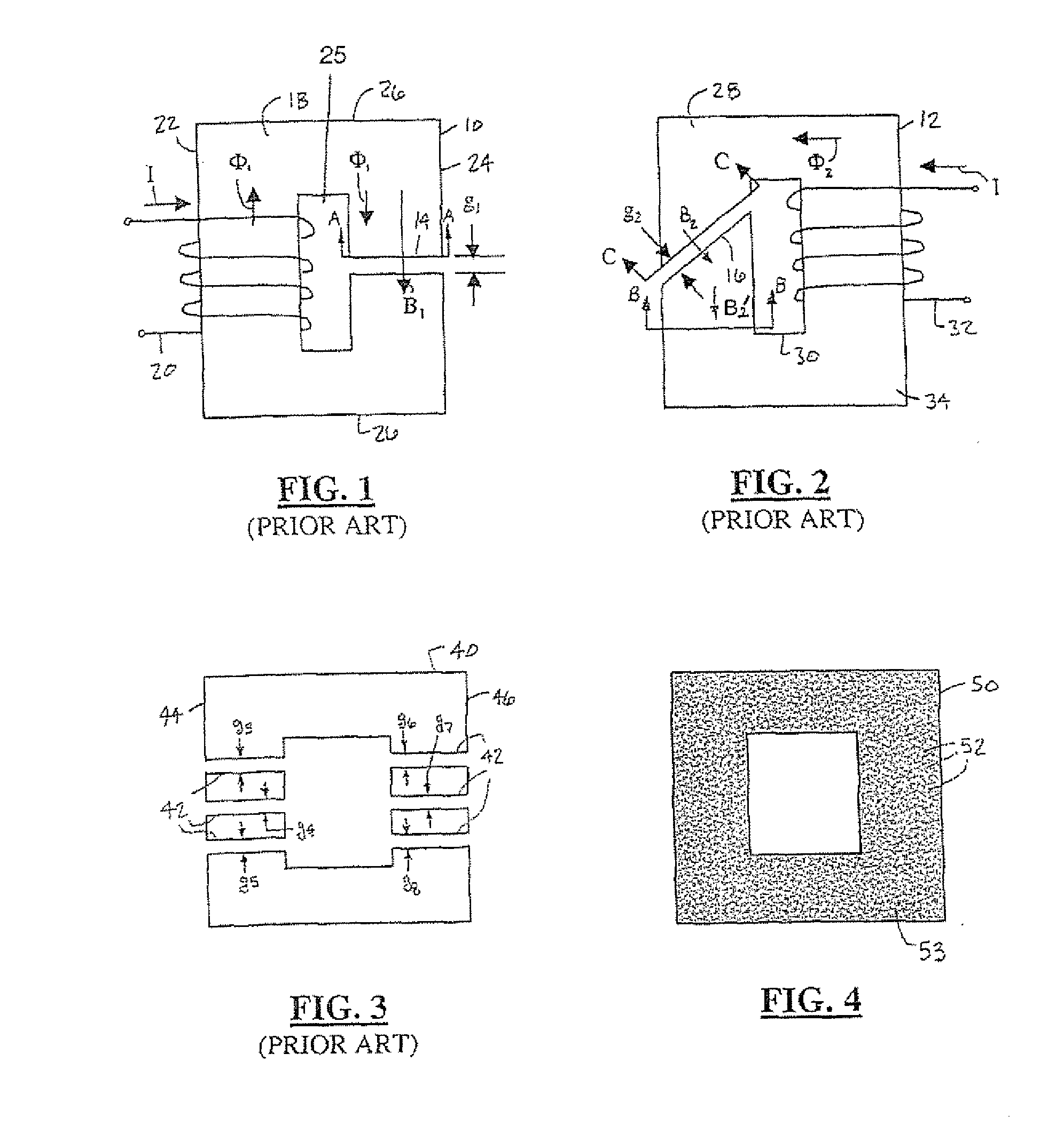
[0027]Referring now to FIGS. 1 and 2, side views of a first traditional inductor 10 and a second traditional inductor 12. The first inductor 10 has a lateral gap 14 that is oriented approximately perpendicular to a magnetic flux path Φ1. The second inductor 12 has a tilted gap 16. The first inductor 10 includes a first core 18 and a first window 25 winding 20 that are rectangularly-shaped. The winding 20 is wound about a first member 22 of the first core 18. The lateral gap 14 extends across a second member 24 opposite the first member 22. The magnetic flux flow path Φ1 follows and is defined by the members 22, 24, and 26 of the first core 18.

[0028]The second inductor 12 is similar to the first inductor 10. However, instead of having a perpendicularly oriented gap, the second inductor 12 has the diagonally oriented or tilted gap 16. The tilted gap 16 is in a non-perpendicular arrangement relative to the magnetic flux flow path Φ2 passing through the second inductor 12. The second in...


PUM

PropertyMeasurementUnit
saturation flux densityaaaaaaaaaa
magnetic fluxaaaaaaaaaa
permeabilityaaaaaaaaaa

Abstract

An inductor L may include a core 140 that has a member 141 with multiple material zones 142. The material zones 142 have associated saturation flux density and permeability. A winding 194 is coupled to the member 141 and is configured for magnetic flux generation in the core 140. An inductor 180 may also or alternatively include a core 192, which has a member 198 with a gap 188, and a permeability-varying member 182. The core 192 has a first saturation flux density. The permeability-varying member 182 is disposed within the gap 188 and has a second saturation flux density that is less than the first saturation flux density.

Description

TECHNICAL FIELD[0001]The present invention relates to vehicle and non-vehicle electronic and electrical systems, components, and circuits. More particularly, the present invention is related to the effective permeability and thus the inductance of inductor core structures.BACKGROUND OF THE INVENTION[0002]A variety of inductor structures currently exist and are utilized throughout industry for numerous purposes. The inductors may be utilized, for example, in hybrid electric vehicles, fan drives, washing machines, refrigerators, and other various machines and equipment to improve efficiency and performance, to minimize noise, or to perform other tasks commonly associated therewith.[0003]An inductor typically is formed of a ferromagnetic core, which may be rectangular-shaped, and has one or more windows. One or more windings are wound about associated segments of the core. Electrical current supplied to the windings creates a magnetic flux in the core. To prevent the core from becoming...

Claims


Application Information

Patent Timeline
Patent Type & Authority Applications(United States)
IPC IPC(8): H01F27/24
CPCH01F3/14H01F2003/106H01F38/023H01F27/346H01F3/10H01F27/24
Inventor CHEN, CHINGCHILIANG, FENGDEGNER, MICHAEL
Owner FORD GLOBAL TECH LLC
Why Eureka
Try Eureka