
Liquid crystal display device and driving method of the same

a liquid crystal display and driving method technology, applied in static indicating devices, instruments, non-linear optics, etc., can solve the problems of loss of light use efficiency and image quality degradation, and achieve the effect of suppressing image quality degradation and preventing the occurrence of luminance gradients

Active Publication Date: 2008-03-27
JAPAN DISPLAY CENT INC
View PDF10 Cites 29 Cited by
  • Summary
  • Abstract
  • Description
  • Claims
  • Application Information

AI Technical Summary

Benefits of technology

[0015]The present invention has been made in consideration of the above-described problems, and the object of the invention is to provide a liquid crystal display device and a driving method thereof, to which column inversion or frame inversion, in particular, frame inversion, is applied as a polarity inversion scheme, and which can prevent occurrence of a luminance gradient in a display image when a field sequential driving method is adopted, thus suppressing degradation in image quality.
[0017]According to a second aspect of the present invention, there is provided a driving method of a liquid crystal display device including a liquid crystal display panel including a pair of substrates and a liquid crystal layer held between the pair of substrates; an area light source device which illuminates the liquid crystal display panel; a driving unit which drives the liquid crystal display panel and the area light source device; and a control unit which controls the driving unit, the liquid crystal display panel including a plurality of display pixels which are arrayed in a matrix, the method comprising: causing the control unit to successively turn on plural kinds of light sources, which are provided in the area light source device, in one frame period; controlling the driving unit to execute, with the same polarity, video signal write for writing a video signal in the plurality of display pixels and reset signal write for writing a reset signal in the plurality of display pixels after the video signal write, in a period in which one of the plural kinds of light sources is turned on in the one frame period; and reversing a polarity of potential of the plurality of display pixels between frame periods.
[0018]The invention can provide a liquid crystal display device and a driving method thereof, to which column inversion or frame inversion, in particular, frame inversion, is applied as a polarity inversion scheme, and which can prevent occurrence of a luminance gradient in a display image when a field sequential driving method is adopted, thus suppressing degradation in image quality.

Problems solved by technology

In the ordinary color filter method, since white backlight passes through RGB color filters, a loss occurs in light use efficiency.
In a liquid crystal display device which adopts the field sequential method, in a case where column inversion or frame inversion is executed as a polarity inversion scheme, image quality may deteriorate, in some cases, due to a luminance gradient occurring in a display image.

Method used


Image

  • Liquid crystal display device and driving method of the same
  • Liquid crystal display device and driving method of the same
  • Liquid crystal display device and driving method of the same

Examples


first embodiment

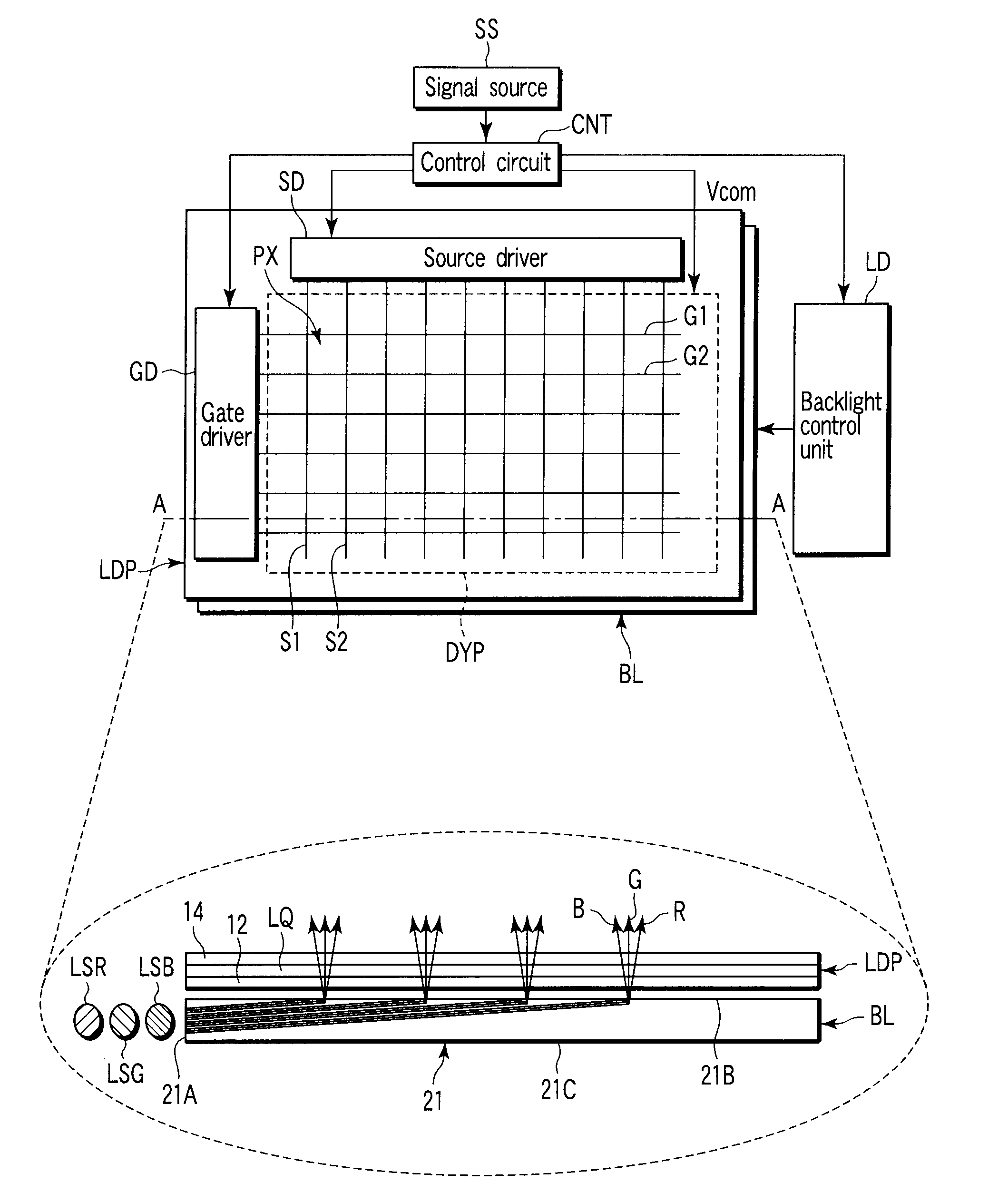
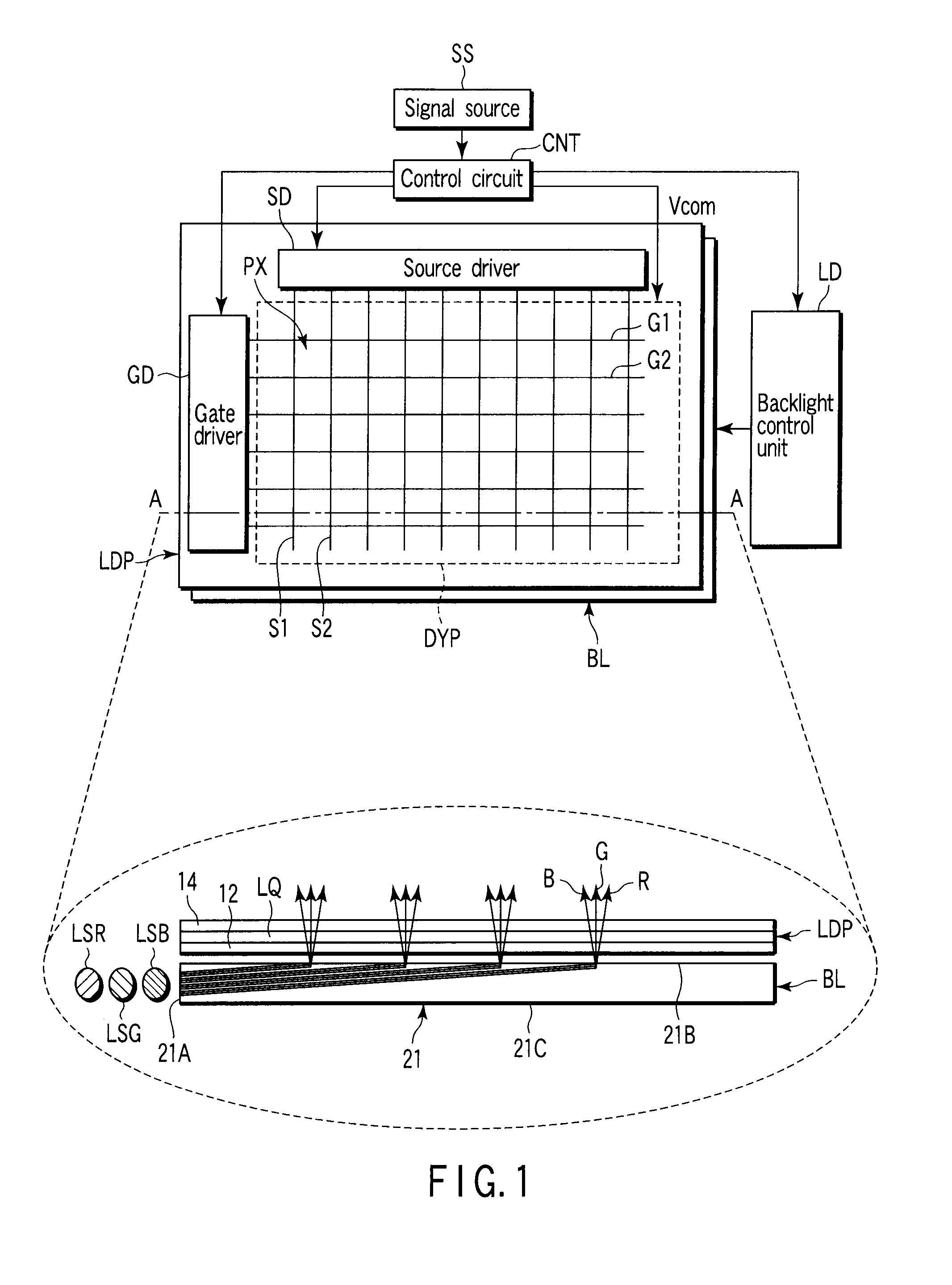
[0026]A liquid crystal display device according to the present invention will now be described with reference to the accompanying drawings. FIG. 1 schematically shows an example of the structure of a liquid crystal display device according to the embodiment. FIG. 1 contains a plan view of the liquid crystal display device, and a cross-sectional view taken along line A-A in the plan view. As is shown in FIG. 1, the liquid crystal display device according to the embodiment includes a liquid crystal display panel LDP and a backlight BL which illuminates the liquid crystal display panel LDP.

[0027]The liquid crystal display panel LDP includes a pair of substrates, i.e. an array substrate 12 and a counter-substrate 14, and a liquid crystal layer LQ which is held between the array substrate 12 and the counter-substrate 14. In the liquid crystal display device according to the embodiment, the liquid crystal layer LQ includes an OCB (Optically Compensated Bend) liquid crystal.

[0028]Further, ...

second embodiment

[0108]In the liquid crystal display device however, it is necessary that the number of times of batch-write of the polarity inversion signal within one frame period be set at an odd number, thereby to suppress the occurrence of flicker.

[0109]In the liquid crystal display devices according to the first and second embodiments, the polarity inversion of the driving voltage is executed, for example, by cyclically reversing the pixel voltage relative to the counter-voltage. Alternatively, the polarity inversion may be executed by varying the counter-voltage. In this case, too, the same advantageous effects as in the first and second embodiments can be obtained.

[0110]Various inventions can be made by properly combining the structural elements disclosed in the embodiments. For example, some structural elements may be omitted from all the structural elements disclosed in the embodiments. Furthermore, structural elements in different embodiments may properly be combined.


PUM


Abstract

A liquid crystal display device includes a liquid crystal display panel (LCD panel), an area light source device which illuminates the LCD panel, a driving unit which drives the LCD panel and the area light source device, and a control unit which controls the driving unit. The LCD panel includes display pixels. The area light source device includes plural kinds of light sources which are successively turned on in one frame period. The control unit includes means for controlling the driving unit in a manner to execute video signal write and reset signal write after the video signal write, in a period in which one of the plural kinds of light sources is turned on in the one frame period. The video signal write and the reset signal write are executed with the same polarity, and a polarity of potential of the display pixels is reversed between frame periods.

Description

CROSS-REFERENCE TO RELATED APPLICATIONS[0001]This application is based upon and claims the benefit of priority from prior Japanese Patent Application No. 2006-261076, filed Sep. 26, 2006, the entire contents of which are incorporated herein by reference.BACKGROUND OF THE INVENTION[0002]1. Field of the Invention[0003]The present invention relates generally to a liquid crystal display device and a method of driving the same, and more particularly to an active-matrix liquid crystal display device and a method of driving the same.[0004]2. Description of the Related Art[0005]In recent years, mobile products in which liquid crystal panels are built, such as small-sized game machines, portable PCs and mobile phones, have been quickly gaining in popularity.[0006]In general, the liquid crystal display panel is configured such that a liquid crystal layer is held between an array substrate and a counter-substrate. In the case where the liquid crystal display panel is of an active matrix type, ...

Claims


Application Information

Patent Timeline
IPC IPC(8): G02F1/141
CPCG09G3/3406G09G3/3611G09G3/3614G09G2320/0247G09G2310/0235G09G2310/061G09G2310/08G09G2300/0491
Inventor TANAKA, YUKIONAKAO, KENJIFUKAMI, TETSUO
Owner JAPAN DISPLAY CENT INC
Learn More