Container Carrying Equipment

Inactive Publication Date: 2008-03-27
HIRATA & CO LTD
View PDF4 Cites 19 Cited by
  • Summary
  • Abstract
  • Description
  • Claims
  • Application Information

AI Technical Summary

Benefits of technology

[0015] Further, during a period in which the container is removed from the conveyor line, lowered to the load port, and is returned to the conveyor line through operation of the lifting apparatus and the pallet insertion/removal means, movement along the conveyor line of a container on the upstream side of the conveyor is not hindered.
[0016] Moreover, since the container is conveyed by the conveyor in a state in which the container is placed on the pallet, the container is transported in a more stable manner.
[0018] As described above, according to the container transport apparatus of the present invention, through cooperation of two types of apparatus and means; i.e., the lifting apparatus and the pallet insertion/removal means, the container on the conveyor can be transferred to the load port of a predetermined processing apparatus, and the container can be transferred

Problems solved by technology

If dust or impurities such as vaporized organic substances adhere to surfaces of semiconductor wafers, the wafers are contaminated, resulting in lowered yield of products; i.e., lowered non-defective ratio.
Incidentally, since maintaining such a clean room requires high cost, a matter of great interest is reducing the size of the clean room through rational arrangement of a transport apparatus, processing apparatuses, and working areas for workers.
Therefore, only a single combination of these apparatuses and mechanisms is required to

Method used


Image

  • Container Carrying Equipment
  • Container Carrying Equipment
  • Container Carrying Equipment

Examples


embodiment

[0030] Next, an embodiment of the present invention will be described.

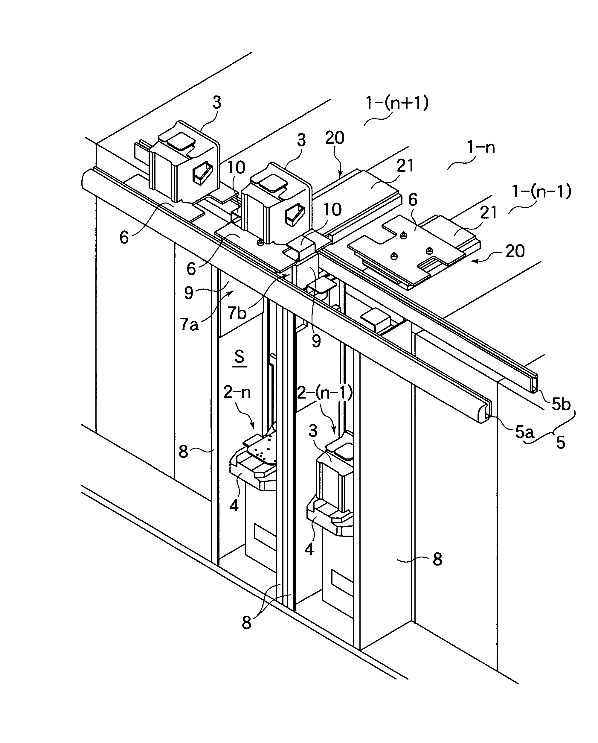
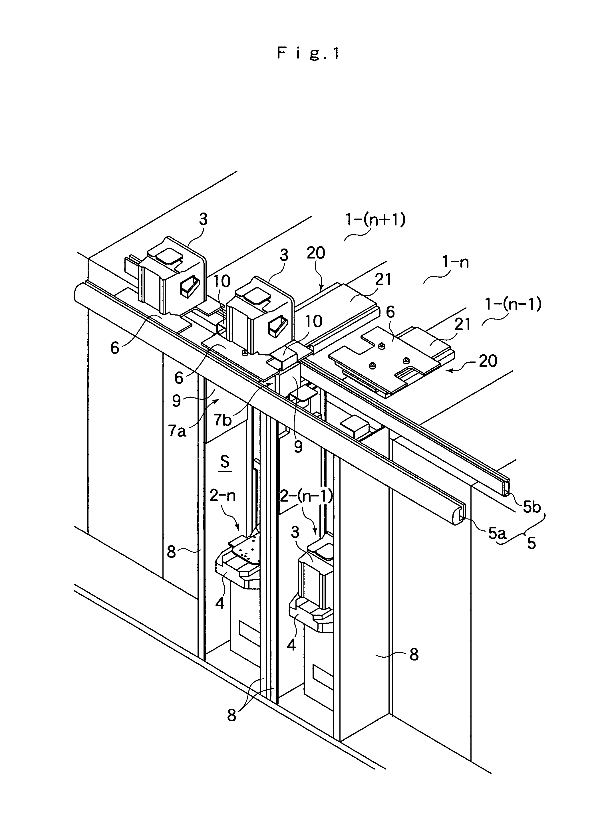
[0031] A bay area of a semiconductor manufacturing apparatus to which a container transport apparatus of the present embodiment is applied is configured in the form of a clean room, and contains a plurality of processing apparatuses for performing various processes on a semiconductor wafer to form integrated circuits thereon. In general, these processing apparatuses are aligned and arranged in a certain direction, and / or a plurality of groups each including a plurality of processing apparatuses aligned and arranged in a certain direction are disposed in parallel. In this manner, the layout of the processing apparatuses is determined so as to minimize the footprint of workpiece transport along the processing steps. In general, a semiconductor manufacturing apparatus is configured by connecting a plurality of such bay areas.

[0032] Meanwhile, a plurality of semiconductor wafers (workpieces) are typically stored in ...


PUM


Abstract

A container 3 airtightly stores articles, such as semiconductor wafers and liquid-crystal display panels, which are required to be transported with their surface kept uncontaminated. A container transport apparatus is used to transport the container 3 between a plurality of processing apparatuses 1-n within a bay area. The container transport apparatus includes a conveyor 5, which is arranged in a ceiling space within the bay area along a direction of arrangement of the plurality of processing apparatuses 1-n and which is adapted to move the container 3 in a state where the container 3 is placed on a pallet 6. The container transport apparatus also includes a lifting apparatus 7, which is provided for each load port 4 of the plurality of processing apparatuses 1-n disposed under the conveyor 5 and which is adapted to lift and lower the container 3 between the load port 4 and the conveyor 5, and a pallet insertion/removal means 20 for inserting the pallet 6 into a space above the conveyor 5 and removing the pallet 6 therefrom.

Description

TECHNICAL FIELD [0001] The present invention relates to a container transport apparatus (container carrying equipment), and more particularly to a container transport apparatus which is used to transport, between a plurality of processing apparatuses, a container which airtightly stores articles, such as semiconductor wafers and liquid-crystal display panels, which are required to be transported with their surface kept uncontaminated. BACKGROUND ART [0002] If dust or impurities such as vaporized organic substances adhere to surfaces of semiconductor wafers, the wafers are contaminated, resulting in lowered yield of products; i.e., lowered non-defective ratio. In order to overcome this problem, when wafers are conveyed between a plurality of different processing apparatuses, a plurality of wafers are accommodated within a highly clean, sealed container, which is called a FOUP (Front Opening Unified Pod), and are conveyed together with the FOUP. Further, it is important to maintain th...

Claims


Application Information

Patent Timeline
IPC IPC(8): H01L21/677
CPCH01L21/67733H01L21/67775H01L21/67736
Inventor TACHIBANA, KATSUYOSHI
Owner HIRATA & CO LTD
Why Eureka
Try Eureka