Water saver fill valve and assembly

a fill valve and water saving technology, applied in the field of plumbing fixtures, can solve the problems of water running back out of the tank, the fill valve cannot be opened and closed, and the tank cannot be refilled itself, so as to prevent the refilling of the tank

Active Publication Date: 2008-04-03
LAVELLE IND
View PDF19 Cites 12 Cited by
  • Summary
  • Abstract
  • Description
  • Claims
  • Application Information

AI Technical Summary

Benefits of technology

[0008]A primary objective of the present invention is to provide an improved fill valve and assembly that has the ability to shut off the fill valve in situations where a catastrophic leak in the flush valve assembly or other tank orifice results in the tank being unable to fill itself. It is another objective of the present invention to provide an improved fill valve and assembly that also has the ability to prevent refilling of the tank in situations where a very slow leak exists in the flush valve assembly or elsewhere in the tank. It is yet another objective to provide such an assembly where the primary objective stated above can be accomplished by a modification of an existing fill valve design. It is still another objective to provide an improved fill valve of this type that can be used in toilet fixtures of original manufacture as well as in the after market.

Problems solved by technology

One limitation of the fill valve construction discussed above is that there is no ability for the fill valve to seal off the pilot orifice in situations where a catastrophic leak in the flush valve assembly or other tank orifice results in the tank being unable to refill itself.
In this mode, the fill valve could continue to allow water to run into the tank with the result that this water is simply running back out of the tank and is wasted.
A similar limitation of the fill valve construction discussed above is that there is no ability to shut off the fill valve in situations where a slow leak exists in the flush valve due to wear of the flush valve, improper seating, or some other minor malfunction of the flush valve assembly.
In this mode, the tank will very slowly leak water through the flush valve assembly and require intermittent functioning of the fill valve to compensate for this slow leak condition, wasting a potentially large amount of water over time.

Method used


Image

  • Water saver fill valve and assembly
  • Water saver fill valve and assembly
  • Water saver fill valve and assembly

Examples


Embodiment Construction

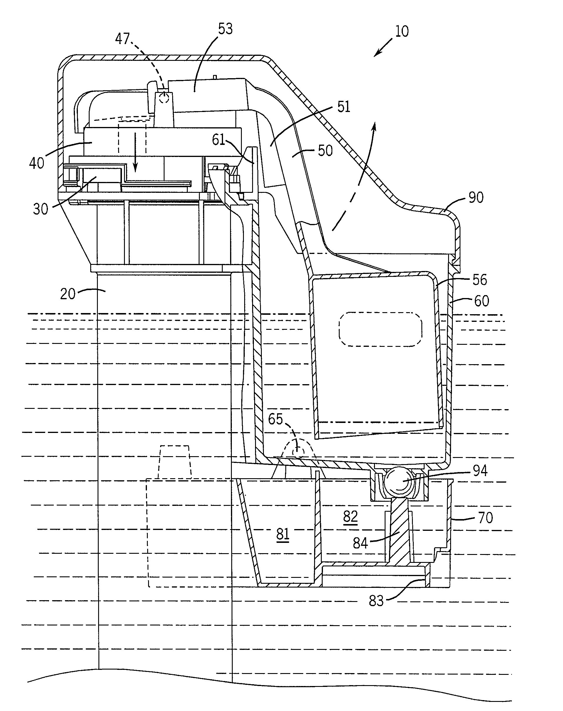
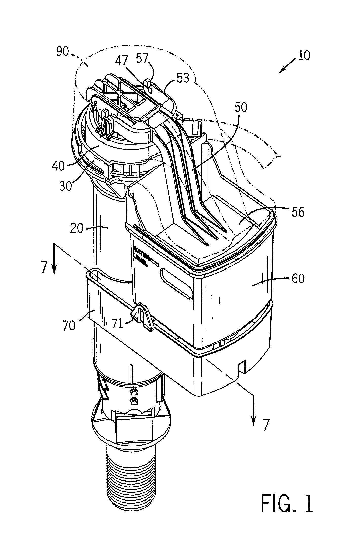
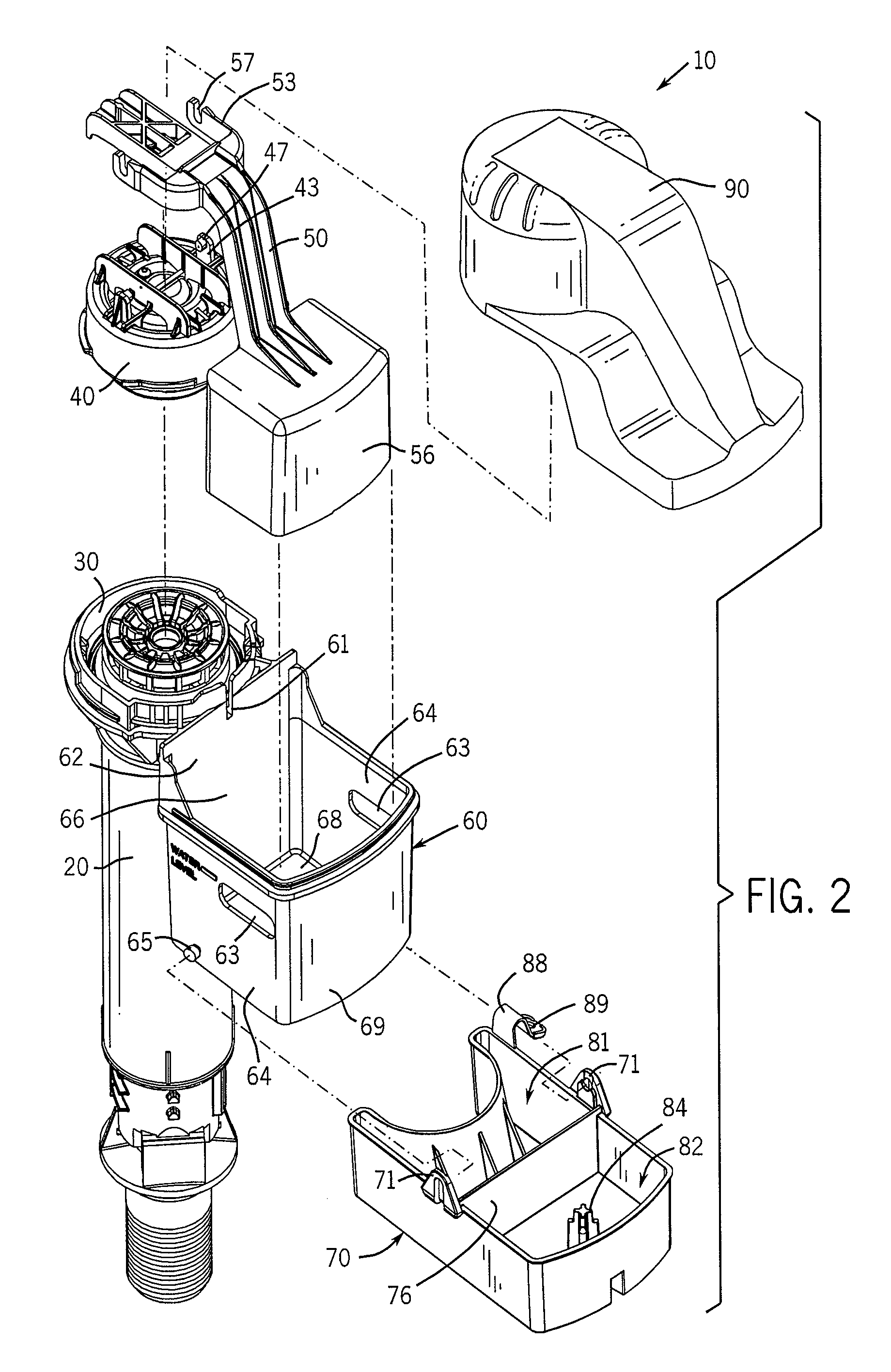
[0026]Referring now to the drawings in detail, wherein like-numbered elements refer to like elements throughout, FIGS. 1 and 2 illustrate an improved fill valve assembly and apparatus that is constructed in accordance with the preferred embodiment of the invention, the assembly and apparatus being designated generally by the numeral 10. The overall fill valve assembly and apparatus 10 comprises an improvement over fill valves of the type generally disclosed and covered in U.S. Pat. No. 6,003,541 entitled “Unitary Float and Arm for Float Operated Valve,” U.S. Pat. No. 5,975,125 entitled “Combined Filter and Noise Suppressor for Fill Valve,” U.S. Pat. No. 5,836,346 entitled “Pilot Operated Diaphragm Fill Valve” and U.S. Pat. No. 5,715,859 entitled “Adjustable Fill Valve Assembly.” Each of the foregoing patents, and any relevant disclosure contained in it, is incorporated herein by reference as though fully set forth.

[0027]The improved fill valve 10 is designed to prevent water wastage...


PUM


Abstract

An improved fill valve has a pivot valve body that is pivotally suspended immediately below a float housing and is movable between two positions. In a first position, the pivot valve body blocks the flow of water from the float housing. In a second position, the pivot body allows the flow of water from the float housing. The pivot valve body has two top compartments, each separated from the other by a wall. The first compartment retains an amount of water in it. The second compartment functions as a water flow restriction apparatus and includes an upwardly-extending member for sealing off a check valve that is disposed within the bottom of the float housing. The fill valve also includes structural elements that allow the water to trickle into the float housing at a very slow rate. The fill valve can be re-set for normal toilet tank operation.

Description

FIELD OF THE INVENTION[0001]The present invention relates generally to plumbing fixtures and to the component parts that are used in them. More particularly, it relates to an improved fill valve and assembly for flush systems used in gravity flush toilets. It also relates to such a fill valve and assembly that prevents water wastage under conditions where the toilet tank is prevented from filling properly due to a catastrophic flush valve leak or tank leak. It also relates to such a fill valve and assembly that limits or reduces water leakage under conditions where a relatively small flush valve leak exists.BACKGROUND OF THE INVENTION[0002]Conventional toilets typically employ a generally rectangular porcelain tank mounted immediately above a porcelain bowl from which a quantity of water is rapidly drained in order to flush waste from the bowl into the sewer system. One very common design uses a flapper valve made of an elastomeric material that normally covers the drain outlet of t...

Claims


Application Information

Patent Timeline
Patent Type & Authority Applications(United States)
IPC IPC(8): F16K31/18
CPCF16K31/26E03D1/32F16K31/34Y10T137/7404Y10T137/7384Y10T137/7365
Inventor NICHOLS-ROY, DAVIDWOODS, DENNIS D.TORRES, ALBERTO C.
Owner LAVELLE IND
Why Eureka
Try Eureka