Pneumatic air exhaust system

A pneumatic and damper technology, applied in the field of exhaust, can solve the problem that the exhaust system cannot fully exhaust and exchange air in a timely manner, and achieve the effect of ensuring smooth exhaust, preventing airflow recharge, and ensuring freshness.

Inactive Publication Date: 2009-04-29
北京恩湾科技有限公司
View PDF0 Cites 3 Cited by
  • Summary
  • Abstract
  • Description
  • Claims
  • Application Information

AI Technical Summary

Problems solved by technology

[0003] The present invention aims to solve the problem that the existing exhaust system cannot exhaust and ventilate in a timely and comprehensive manner, and provides a pneumatic exhaust system that prevents the exhaust from refilling

Method used


Image

  • Pneumatic air exhaust system

Examples


Embodiment Construction

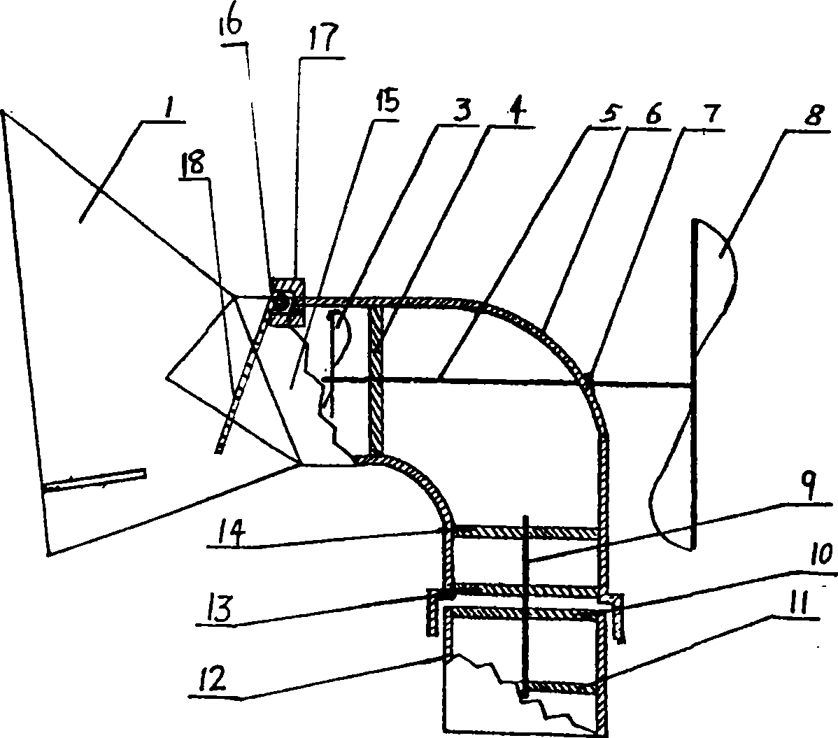
[0014] The pneumatic exhaust system includes a fixed air channel 12, a rotating air channel 6, an exhaust fan 3, a pneumatic fan 8, an empennage 1, a damper 16 and an air outlet.

[0015] The lower end of the fixed air channel 12 is connected to the indoor chamber, and its upper end is connected to a rotating air channel 6 . The connection mode is that the fixed air passage is provided with a first support 11 for the fixed air passage and a second support 10 for the fixed air passage, and the lower end of the fixed shaft 9 is fixed on the above two supports; The first support 13 of the airway and the second support 14 of the rotating airway, the upper end of the fixed shaft 9 is fitted on the above-mentioned two rotating airway supports through a bearing; or the lower end of the fixed shaft 9 is fitted on the above-mentioned two fixed airway supports through a bearing; or Both ends of the fixed shaft are matched by bearings, and the lower end of the rotating air passage is sle...


PUM


Abstract

The invention relates to the technical field of air exhaust, in particular to a wind-powered exhaust system. The invention solves the problem that the prior exhaust system can not achieve on-time and overall exhaust and ventilation by providing a wind-powered exhaust system capable of preventing exhausted air from being recharged. The wind-powered exhaust system comprises a fixed air passage, an exhaust fan and air outlet, wherein an upper end of the fixed air passage is connected with a rotary air passage, and an air door is arranged at the air outlet. The wind-powered exhaust system has the advantages of no secondary pollution, environmental protection, simple maintenance and reduced labor cost, economization and practicality, effective and complete discharge of dirt air in the air passage, prevention of air-flow recharge, and ensured smooth air discharge and freshness of air.

Description

technical field [0001] The invention relates to the technical field of exhaust, in particular to a pneumatic exhaust system. Background technique [0002] In order to improve the living environment, the buildings are generally equipped with exhaust devices with different specifications. However, the existing exhaust devices have fixed air outlets, resulting in no way to change the direction of the wind. When the wind direction changes, when the exhaust air When the windward face faces the ground and the external wind is strong, it will cause difficulty in exhausting the air, which will easily cause the backflow of the airflow, and the air cannot be updated in time, resulting in poor exhaust, which will block the airflow and affect the exhaust effect, which is not conducive to the people living in it. people's health. Contents of the invention [0003] The present invention aims to solve the problem that the existing exhaust system cannot exhaust and ventilate in a timely ...

Claims


Application Information

Patent Timeline
Patent Type & Authority Applications(China)
IPC IPC(8): F24F7/06F24F13/10
Inventor 陈华黄涛
Owner 北京恩湾科技有限公司
Why Eureka
Try Eureka