Linear damper for check valve

a damper and check valve technology, applied in the field of check valves, can solve problems such as noise and wear

Inactive Publication Date: 2008-04-03
HONEYWELL INT INC
View PDF14 Cites 20 Cited by
  • Summary
  • Abstract
  • Description
  • Claims
  • Application Information

AI Technical Summary

Benefits of technology

[0007]In yet another embodiment, and by way of example only, a damping system, for a valve with a flapper movable between an open position and a closed position, comprises a main body and a piston. The main body has at least an inner wall that defines a chamber having fluid therein. The main body is coupled to the flapper, and is configured to move therewith. The piston is disposed at least partially within the chamber. The piston is configured to move within the chamber in a direction opposite the direction of movement of the main body when the flapper approaches the open position or the closed position, to thereby compress the fluid in a section of the chamber and slow movement of the main body. Movement of the flapper is thereby slowed when approaching the open position or the closed position.

Problems solved by technology

Such check valves, while generally safe, reliable, and robust, can experience some wear and / or noise, for example when the valves open and close.

Method used


Image

  • Linear damper for check valve
  • Linear damper for check valve
  • Linear damper for check valve

Examples


Embodiment Construction

[0020]The following detailed description of the invention is merely exemplary in nature and is not intended to limit the invention or the application and uses of the invention. Furthermore, there is no intention to be bound by any theory presented in the preceding background or the following detailed description. In this regard, although the invention is described herein as being implemented in an air distribution system, it will be appreciated that it could also be implemented in any one of numerous other types of systems that direct the flow of various types of fluid, both within or apart from an aircraft, and / or any one of numerous other types of vehicles or other types of apparatus or systems.

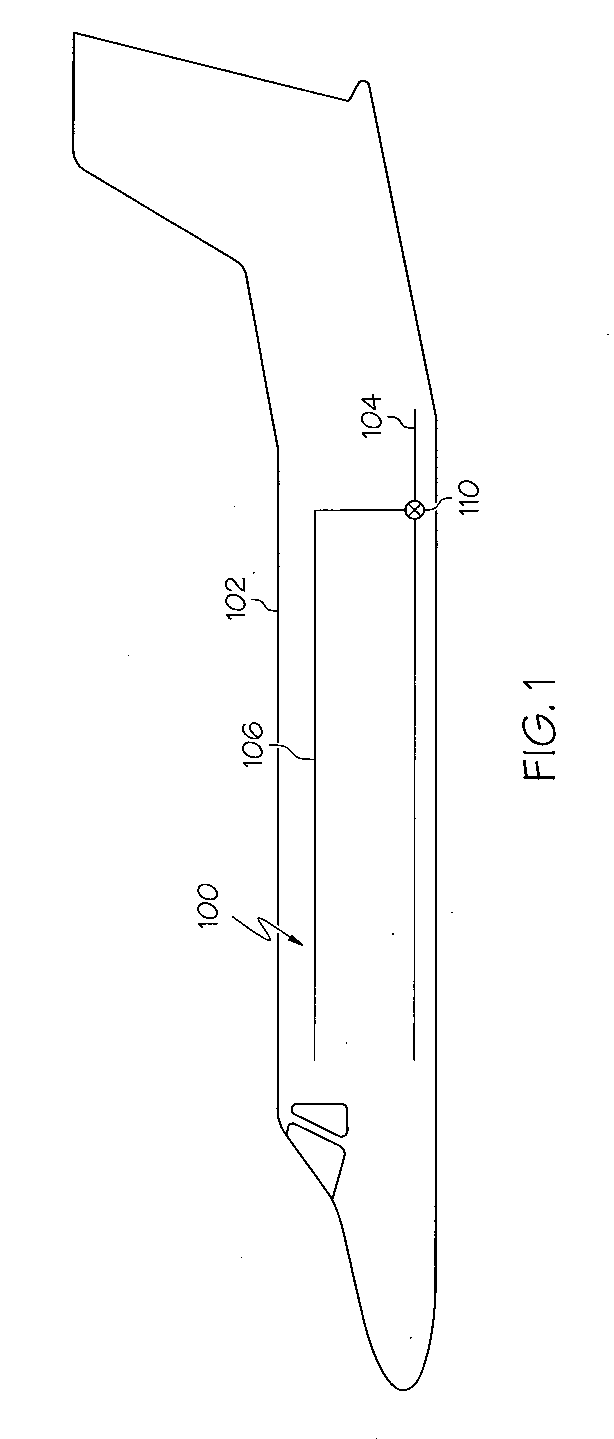
[0021]FIG. 1 is a simplified schematic diagram illustrating an air distribution system 100 disposed within an aircraft 102. The air distribution system 100 includes an inlet duct 104, one or more outlet ducts 106 (only one of which is shown here), and a valve 110 positioned in the duct 106....


PUM


Abstract

A damping system, for a valve with a flapper movable between an open position and a closed position, comprises a main body and a piston. The main body has at least an inner wall that defines a chamber having fluid therein. The main body is coupled to the flapper, and is configured to move therewith. The piston is disposed at least partially within the chamber. The piston is configured to move within the chamber in a direction opposite the direction of movement of the main body when the flapper approaches the open position or the closed position, to thereby compress the fluid in a section of the chamber and slow movement of the main body. Movement of the flapper is thereby slowed when approaching the open position or the closed position.

Description

TECHNICAL FIELD[0001]The present invention relates generally to a check valve and, more particularly, to a check valve with a linear damping mechanism.BACKGROUND[0002]Insert style check valves are used to control air flow in a pneumatic system, and may be installed for the purpose of reducing system weight and costs. For example, the check valves may be used to replace larger, body style check valves that are in ducts of the pneumatic system. Generally, check valves operate by moving between a closed position, where the valve seals the duct and prevents air from flowing in a reverse direction, and an open position, where the valve unseals the duct and allows air flow in a forward direction. Such check valves, while generally safe, reliable, and robust, can experience some wear and / or noise, for example when the valves open and close.[0003]Accordingly, there is a need for a check valve with reduced wear and / or noise when opening and closing. The present invention addresses at least t...

Claims


Application Information

Patent Timeline
Patent Type & Authority Applications(United States)
IPC IPC(8): F16K21/10
CPCB64D13/02Y02T50/44F16K15/038Y02T50/40Y10T137/7839Y10T137/785
Inventor DENIKE, STUART K.JIRA, JOSEPH J.MCGONIGLE, G. STEPHENWARRINER, JEREMIAH J.
Owner HONEYWELL INT INC
Why Eureka
Try Eureka