Electric motor mounting structure for vehicles

Active Publication Date: 2008-04-03
MITSUBISHI MOTORS CORP
View PDF13 Cites 55 Cited by
  • Summary
  • Abstract
  • Description
  • Claims
  • Application Information

AI Technical Summary

Benefits of technology

[0018]The present invention has been developed in consideration of this situation, and it is therefore a first object of the invention to provide a structure for mounting an electric moto

Problems solved by technology

However, by the technique of the related document 1, it is difficult to fully utilize the space above the parts-mounting frame (8) because the parts-mounting frame (8) is fixed to the side members (5) at the substantially same level as the side members (5).
On the other hand, although it must be eff

Method used


Image

  • Electric motor mounting structure for vehicles
  • Electric motor mounting structure for vehicles
  • Electric motor mounting structure for vehicles

Examples


Example

[0029]The embodiment of the present invention will now be described with reference to the accompanying drawings.

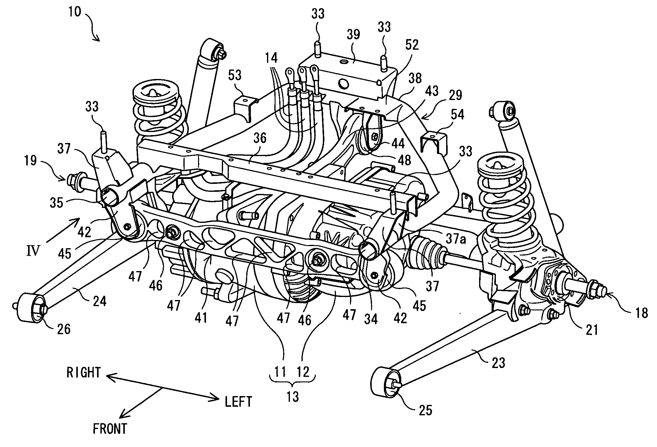
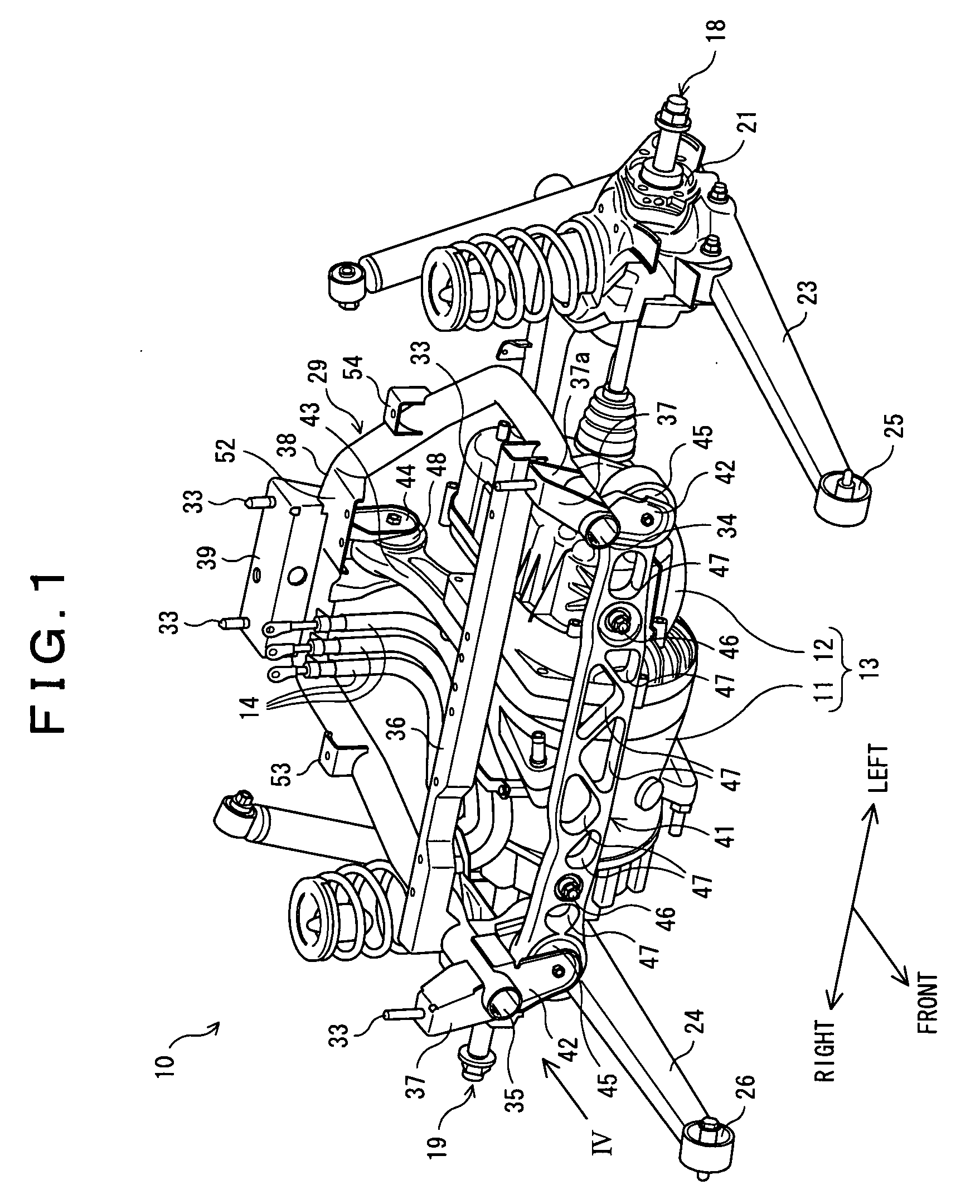
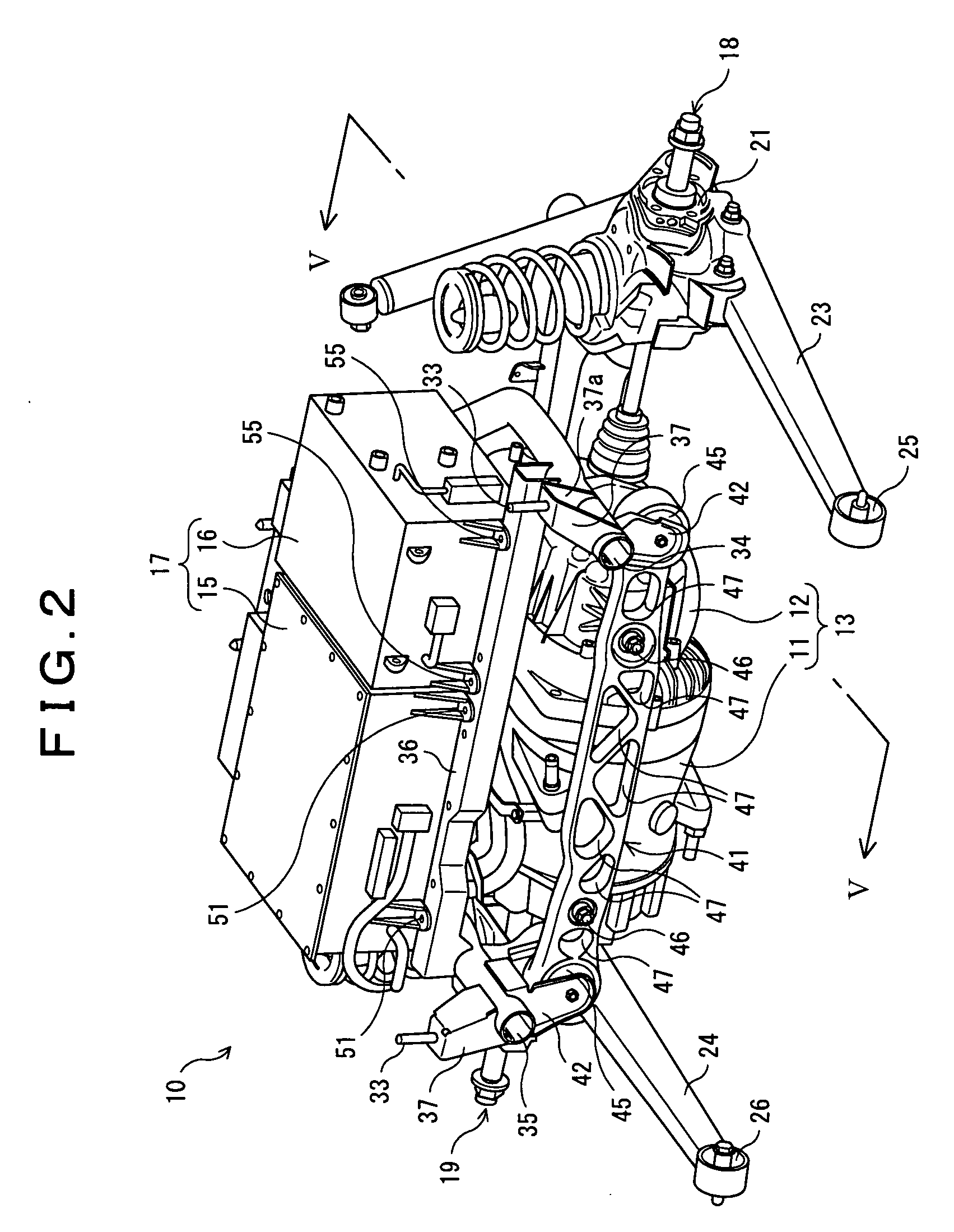
[0030]As shown in FIG. 1 and FIG. 2, a motor unit 13, which includes an electric motor 11 and a reduction gear box 12, is installed at a rear side of a vehicle 10.

[0031]The electric motor 11, which is connected with a control unit 17 shown in FIG. 2 by the electric cables 14, drives rear wheels (not shown). The electric motor 11 is disposed in such a manner that a rotation axis (not shown) of the motor 11 extends in a width direction of the vehicle 10 (see arrows Left and Right in FIG. 1). Namely, the motor unit 13 is mounted on the vehicle 10 in a transverse layout manner.

[0032]The reduction gear box 12, which is mechanically connected with the electric motor 11 and is also connected with a left-drive-shaft assembly 18 and a right-drive-shaft assembly 19, individually transmits the rotation input from the electric motor 11 to the left-drive-shaft assembly 18 and the right...


PUM


Abstract

A structure for mounting an electric motor in a vehicle, comprises: a mounting frame detachably fixed to a body component of the vehicle by a bolt; an upward-projecting bracket, which is upwardly projected from the mounting frame, being attached to the body component of the vehicle; a bolt hole, in which the bolt is inserted, being formed on the upward-projecting bracket; and a downward-projecting bracket, which is downwardly projected from the mounting frame, being connected to the electric motor. Both the mounting frame and the downward-projecting bracket are set apart from an axis of the bolt hole.

Description

BACKGROUND OF THE INVENTION[0001](1) Field of the Invention[0002]The present invention relates to a structure for mounting an electric motor in vehicles such as Electric Vehicles and Hybrid Vehicles.[0003](2) Description of Related Art[0004]In recent years, techniques related to Electric Vehicles and Hybrid Vehicles have been developed to protect the global environment.[0005]For example, the following related document 1 discloses a structure for mounting an electric motor in a vehicle.[0006]The technique of the related document 1 will now be described briefly. In this part of the description, numerals in brackets correspond to numerals used in figures of the related document 1.[0007]In the related document 1, as shown in FIG. 1 and FIG. 2, a parts-mounting frame (8) is disclosed which is comprised of two lateral frames (9) and a longitudinal frame (10) connecting the frames (9).[0008]The related document 1 also discloses that a motor unit (15) is fixed on the bottom of the parts-mou...

Claims


Application Information

Patent Timeline
IPC IPC(8): B60K1/00
CPCB60K1/00H02K7/006H02K5/00B60K6/22
Inventor TAJI, TOSHIYATAKEDA, ATSUSHI
Owner MITSUBISHI MOTORS CORP
Why Eureka
Try Eureka