Magnetic sweeper

Inactive Publication Date: 2008-04-03
STEELWORKS HARDWARE L L C
View PDF22 Cites 10 Cited by
  • Summary
  • Abstract
  • Description
  • Claims
  • Application Information

AI Technical Summary

Benefits of technology

[0009]The present invention comprises a magnetic sweeper configured to collect magnetic metal debris, such as nails, screws, sheet metal fragments, staples, rivets and the like from a surface, and to permit easy removal of the collected debris from the sweeper.
[0010]In the preferred embodiment, the sweeper of the present invention comprises a non-metallic body, a permanent magnet disposed within the body, a non-metallic cover hingeably mounted to the underside of the body and an integrated latch configured to removably secure the cover to the body. The body further comprises a plurality of low profile wheels mounted at the rear of the body, while the cover further comprises a plurality of wheels extending downwardly beneath the cover towards the front of the body to create a space between the cover and the surface upon which the debris is located.
[0012]In the preferred embodiment, the coupler is configured to modularly and removably engage a handle. In one embodiment, if the magnetic sweeper of the present invention may be used on a work table or other surface in close proximity to the user, the handle is directly connected to the coupler. In another embodiment, an extendable, telescoping extender may be connected between the coupler and the handle. Such an embodiment permits the magnetic sweeper of the present invention to be used on a floor, or to reach beneath a cabinet, tool chest or vehicle. Additionally, the rotation of the boss member within the socket, along with the rotation of the coupler about the boss member, advantageously permits the body of the magnetic sweeper of the present invention to swivel when a rotating force is applied to the handle.

Problems solved by technology

Small magnetic metal objects, such as nails, screws, sheet metal fragments, staples, rivets and the like, often drop to the floor or ground during use and create debris.
If left on the floor or on the ground, such objects, which oftentimes are sharp, may pose a hazard to both people and machinery.
A major drawback associated with this type of magnetic sweeper is that the user has to remove them from the magnet one by one, which is time-consuming and potentially hazardous.
In addition, due to the length of the handle, the magnetic sweeper cannot access places of small height, such as beneath a cabinet, tool chest or the chassis of an automobile.
While the magnetic sweeper disclosed in this patent permits relatively easy operation, it is inconvenient to remove the debris captured by magnets.
However, because the catcher member requires the user to grip the catcher member on both sides in order to remove it from the housing, the user's hand may be injured by sharp ends and edges of the metallic objects when removing the catcher member.
However, none of the disclosed magnetic sweepers are particularly easy to use, lightweight, portable and adaptable for clearing debris from a variety of different locations, including floors, work tables and beneath cabinets, tool chests, vehicles and the like.

Method used


Image

  • Magnetic sweeper
  • Magnetic sweeper
  • Magnetic sweeper

Examples


Embodiment Construction

[0021]While the present invention is susceptible of embodiment in various forms, there are shown in the drawings and will hereinafter be described several preferred embodiments with the understanding that the present disclosure is to be considered an exemplification of the invention and is not intended to limit the invention to the specific embodiments illustrated.

[0022]It should be further understood that the title of this section of the specification, namely, “Detailed Description of the Invention,” relates to a requirement of the United States Patent and Trademark Office, and does not imply, nor should be inferred to limit the subject matter disclosed herein.

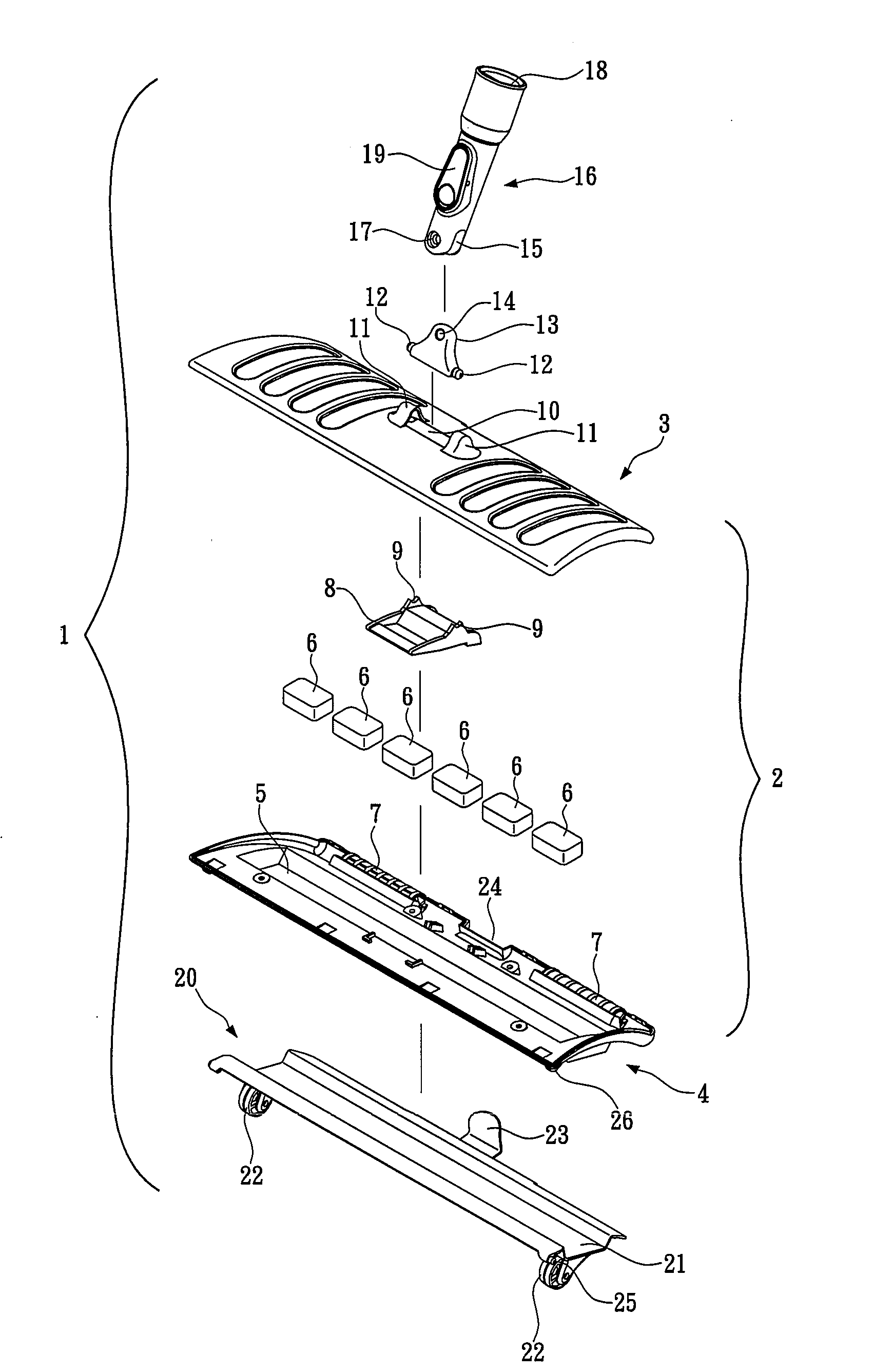
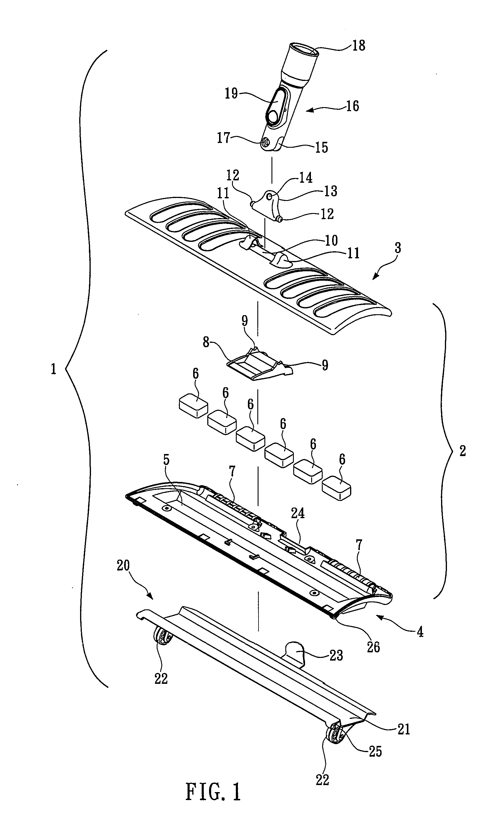
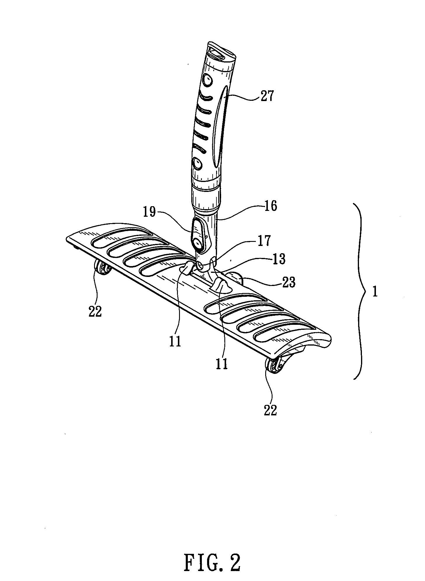
[0023]As shown in FIG. 1, the magnetic sweeper 1 in the preferred embodiment of the present invention comprises a body 2. Body 2 is generally rectangular in shape with a slight arcuate profile. Body 2 is comprised of a top 3 and a bottom 4 which are sealingly engaged. Top 3 and bottom 4 preferably are comprised of a suitably ...


PUM


Abstract

A magnetic sweeper configured to collect magnetic metal debris, such as nails, screws, sheet metal fragments, staples, rivets and the like from a surface, and to permit easy removal of the collected debris from the sweeper is disclosed. The sweeper comprises a non-metallic body, a permanent magnet disposed within the body, a non-metallic cover hingably mounted to the underside of the body and an integrated latch configured to removably secure the cover to the body. The sweeper is configured to removably engage a handle for controlling the sweeper, and in another embodiment, an extendable, telescoping extender may be connected between the coupler and the handle to permit the sweeper to be used in a wide variety of locations. Preferably, the sweeper body is configured to swivel upon application of torque to the handle. In use, the sweeper is passed over metallic debris using the handle to guide the body. As the body passes over such debris, the magnet attracts the debris and holds it against the outer surface of the cover. When debris collection is complete, the cover is unlatched from the body, and swung outwardly from the body, thereby displacing the collected debris to a location outside of the magnetic field of the magnet and permitting the debris to fall away from the cover.

Description

BACKGROUND OF THE INVENTION[0001]The present invention relates to a cleaning device. More particularly, the present invention concerns a magnetic sweeper configured to collect magnetic metal debris, such as nails, screws, sheet metal fragments, staples, rivets and the like from a surface, and to permit easy removal of the collected debris from the sweeper.[0002]Small magnetic metal objects, such as nails, screws, sheet metal fragments, staples, rivets and the like, often drop to the floor or ground during use and create debris. If left on the floor or on the ground, such objects, which oftentimes are sharp, may pose a hazard to both people and machinery. Thus, it is desirable to remove such debris.[0003]Since such debris often is comprised of magnetic materials, the prior art has developed various types of magnetic sweeper devices designed to attract and collect the debris. For example, in its most basic form, such a magnetic sweeper, includes a suction disk, a magnet adhered to a b...

Claims


Application Information

Patent Timeline
IPC IPC(8): B03C1/00
CPCA47L13/41E01H1/14B03C1/30B03C1/08
Inventor LIN, PEI-YINGNGUY, CHANWA
Owner STEELWORKS HARDWARE L L C
Why Eureka
Try Eureka