Multiple light sensors and algorithms for luminance control of mobile display devices

a mobile display device and light sensor technology, applied in the field of display lighting systems, can solve the problems of backlighting of LCDs, display may be too bright, and difficult to view

Inactive Publication Date: 2008-04-03
MOTOROLA INC
View PDF11 Cites 77 Cited by
  • Summary
  • Abstract
  • Description
  • Claims
  • Application Information

AI Technical Summary

Benefits of technology

[0009]The disadvantages of the prior art are overcome by the present invention which, in one aspect, is a method of controlling a lighting unit of a display, in which a maximum value of ambient light intensity is determined. Ambient light intensity is sensed from a first direction relative to the display and from a second direction, different from the first direction, relative to the display. The lighting unit is driven so that light from the lighting unit has a low intensity when the maximum value is less than a first intensity threshold and so that light from the lighting unit has a high intensity, greater than the low intensity, when the maximum value is greater than a second intensity threshold.
[0010]In another aspect, the invention is a method of controlling light intensity from a lighting unit of a display, in which an average intensity of ambient light around the display is determined. The light intensity is changed from a low value to a high value when the light intensity has been set at a low value and the average intensity has a value above a first predetermined threshold and the light intensity is changed from a high value to a low value when the light intensity has been set at a high value and the average intensity has a value below a second predetermined threshold. The first threshold is greater than the second threshold.
[0011]In yet another aspect, the invention is an apparatus for controlling intensity of light from a lighting unit of a display. A first light sensor senses light intensity from a first direction relative to the display and generates a first output corresponding thereto. A second light sensor senses light intensity from a second direction, different from the first direction, relative to the display and generates a second output corresponding thereto. A light intensity control circuit, responsive to the first output and the second output, is configured to determine a maximum value of ambient light intensity sensed from the first light sensor and the second light sensor. The light intensity control circuit is also configured to control an intensity of light generated by the lighting unit of the display so that the intensity is set at a low value when the maximum value is below a first intensity threshold and so that the intensity is set at a high value when the maximum value is above a second intensity threshold.

Problems solved by technology

While backlit LCDs provide a bright display when used away from bright ambient light (such as in a dark room), substantial ambient light can overpower the backlighting of an LCD so as to make it hard to view.
The power to the LEDs may be increased to compensate for intense ambient light, but then the display may be too bright and waste device battery power when used in a darker environment.
However, such manual controls may take up too much space on small devices, such as cellular telephones, and are inconvenient for the user.
However, such systems fail to take into account the fact that the overall ambient light intensity might be considerably different than the intensity detected in the direction in which the sensor is pointed.
Thus, if the sun is behind the user and the light sensor is pointing toward a shaded area, the control circuit will set the backlight intensity to its lowest value, while the ambient light from the sun would make viewing the display quite difficult.
Furthermore, the sensor might become blocked by the user's hand, thereby giving an erroneous reading of ambient light intensity.

Method used


Image

  • Multiple light sensors and algorithms for luminance control of mobile display devices
  • Multiple light sensors and algorithms for luminance control of mobile display devices
  • Multiple light sensors and algorithms for luminance control of mobile display devices

Examples


Embodiment Construction

[0021]A preferred embodiment of the invention is now described in detail. Referring to the drawings, like numbers indicate like parts throughout the views. As used in the description herein and throughout the claims, the following terms take the meanings explicitly associated herein, unless the context clearly dictates otherwise: the meaning of “a,”“an,” and “the” includes plural reference, the meaning of “in” includes “in” and “on.”

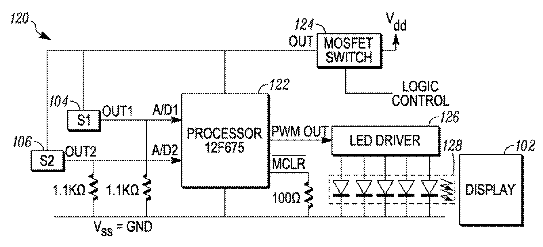
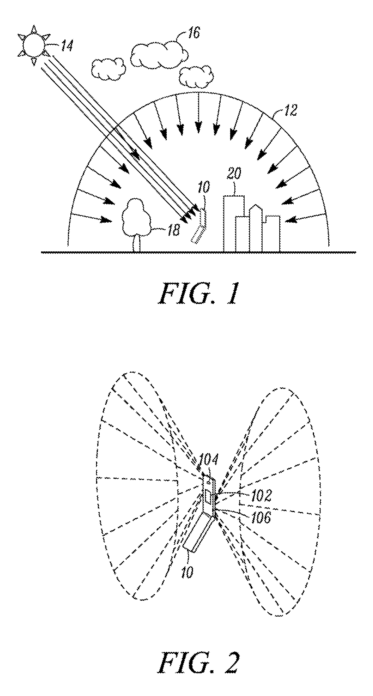
[0022]As shown in FIG. 1, the factors that influence perceptibility of a display 10 include: the intensity and direction of light from the sun 14, the diffusive properties of the atmosphere 12, the passing overhead of clouds 16, the shade of trees 18 and both shadows and reflections from buildings 20. As can be seen from FIG. 1, ambient light intensity cannot always be measured accurately by sensing in only one direction relative to the display. Therefore, one embodiment of a device 10 employing a display 102 that is lighted by a lighting unit, as shown ...


PUM


Abstract

In a method of controlling a lighting unit of a display, a maximum value of ambient light intensity is determined (156). Ambient light intensity is sensed (154) from a first direction relative to the display and from a second direction, different from the first direction, relative to the display. The lighting unit is driven so that light from the lighting unit has a low intensity (172) when the maximum value is less than a first intensity threshold and so that light from the lighting unit has a high intensity, greater than the low intensity, when the maximum value is greater than a second intensity threshold.

Description

BACKGROUND OF THE INVENTION[0001]1. Field of the Invention[0002]The present invention relates to lighting systems for displays and, more specifically to a lighting system that compensates for ambient brightness.[0003]2. Background of the Invention[0004]The liquid crystal display (LCD) is a technology widely-used in providing a user interface to many digital devices, such as cellular telephones and personal data assistants. An LCD typically includes a layer of liquid crystals sandwiched between two layers of glass, one or two polarizing filters (depending on the type of liquid crystal used) and a thin film electrode array.[0005]An LCD produces no light by itself, but only modifies light passing through the LCD to achieve display results. While some LCD applications (e.g., digital watches) rely on ambient light to interact with the LCD, many LCDs require a backlight to illuminate the display. Frequently, the backlight includes a row of light emitting diodes (LEDs) disposed at the base...

Claims


Application Information

Patent Timeline
Patent Type & Authority Applications(United States)
IPC IPC(8): G01J1/28H05B41/36
CPCG09G3/3406G09G2360/144G09G2320/064H05B45/10
Inventor YANG, SENAKINS, ROBERTEMIG, DAVIDKAEHLER, JOHNZHUANG, ZHIMING
Owner MOTOROLA INC
Why Eureka
Try Eureka