System and method for stereoscopic anomaly detection using microwave imaging

a technology of stereoscopic anomaly detection and microwave imaging, which is applied in the field of system and method for stereoscopic anomaly detection using microwave imaging, can solve the problems of inability to detect non-metallic objects, inability to perform physical inspection by security personnel, and prone to false alarms

Inactive Publication Date: 2008-04-03
AGILENT TECH INC
View PDF27 Cites 24 Cited by
  • Summary
  • Abstract
  • Description
  • Claims
  • Application Information

AI Technical Summary

Problems solved by technology

However, physical inspection by security personnel is tedious, unreliable and invasive.
In addition, metal detectors are prone to false alarms, and are not capable of detecting non-metallic objects, such as plastic or liquid explosives, plastic or ceramic handguns or knives and drugs.
Furthermore, X-ray systems pose a health risk, particularly to those people who are repeatedly exposed to X-ray radiation, such as airport personnel.
However, if contraband is positioned on a person or other object such that it appears as an integral part of the object, the operator may not detect the contraband in the 2D or 3D microwave image.
In addition, in automatic threat detection systems, the system may not be able to positively identify areas which are not integral to the imaged object.

Method used


Image

  • System and method for stereoscopic anomaly detection using microwave imaging
  • System and method for stereoscopic anomaly detection using microwave imaging
  • System and method for stereoscopic anomaly detection using microwave imaging

Examples


Embodiment Construction

[0025]As used herein, the terms microwave radiation and microwave illumination each refer to the band of electromagnetic radiation having wavelengths between 0.3 mm and 30 cm, corresponding to frequencies of about 1 GHz to about 1,000 GHz. Thus, the terms microwave radiation and microwave illumination each include traditional microwave radiation, as well as what is commonly known as millimeter wave radiation. In addition, as used herein, the term “microwave imaging system” refers to an imaging system operating in the microwave frequency range, and the resulting images obtained by the microwave imaging system are referred to herein as “microwave images.”

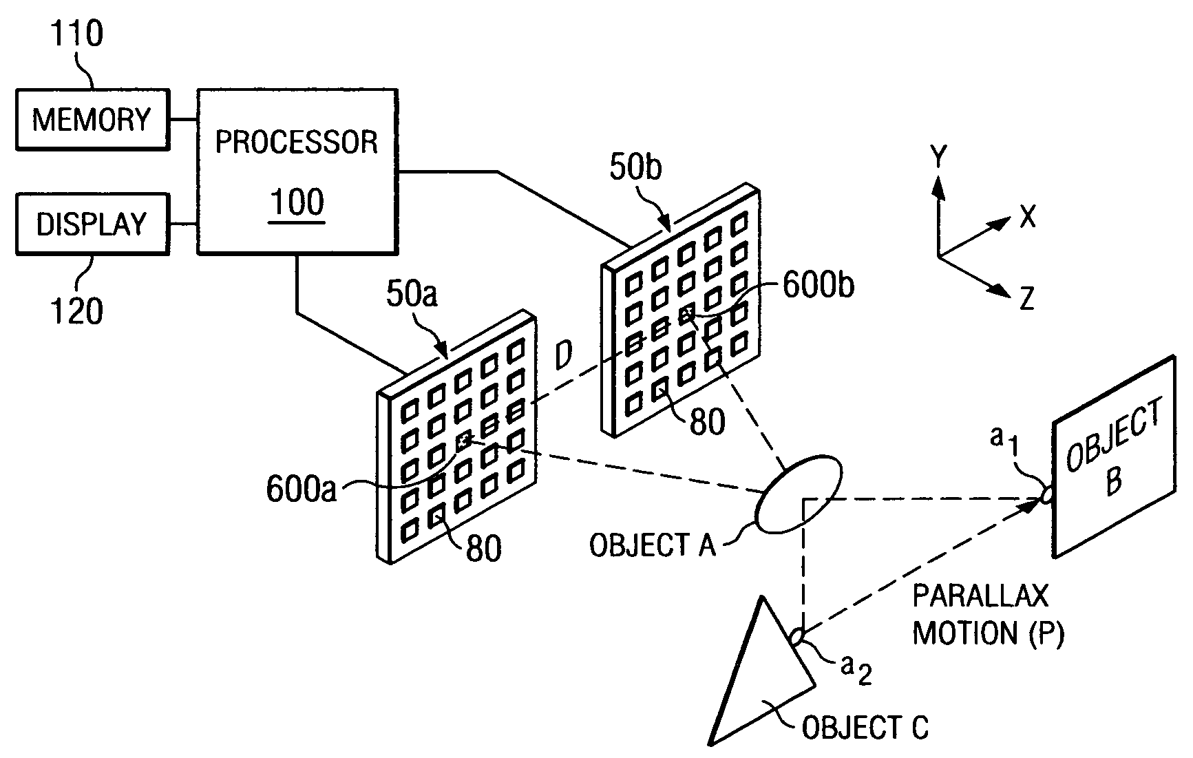
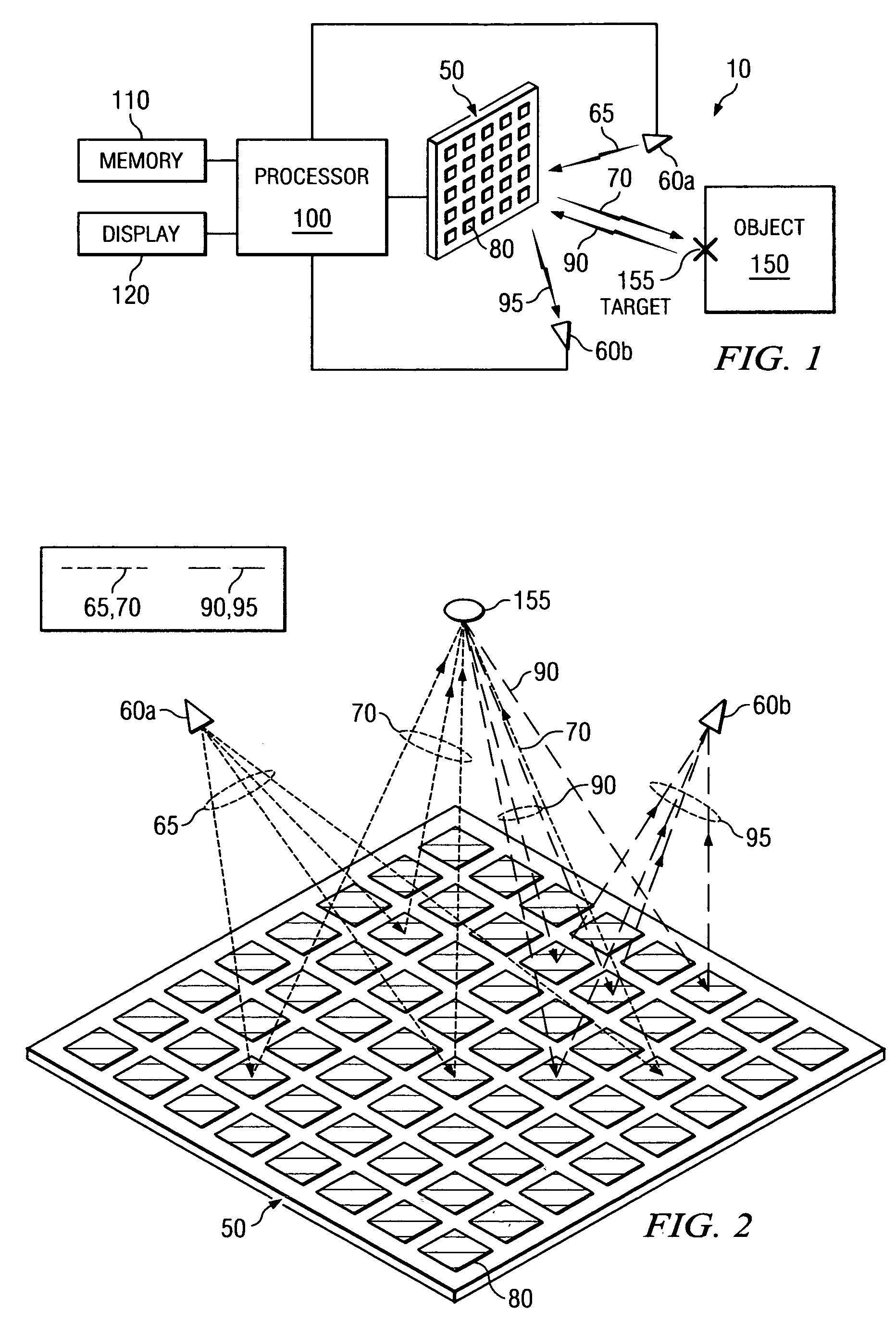
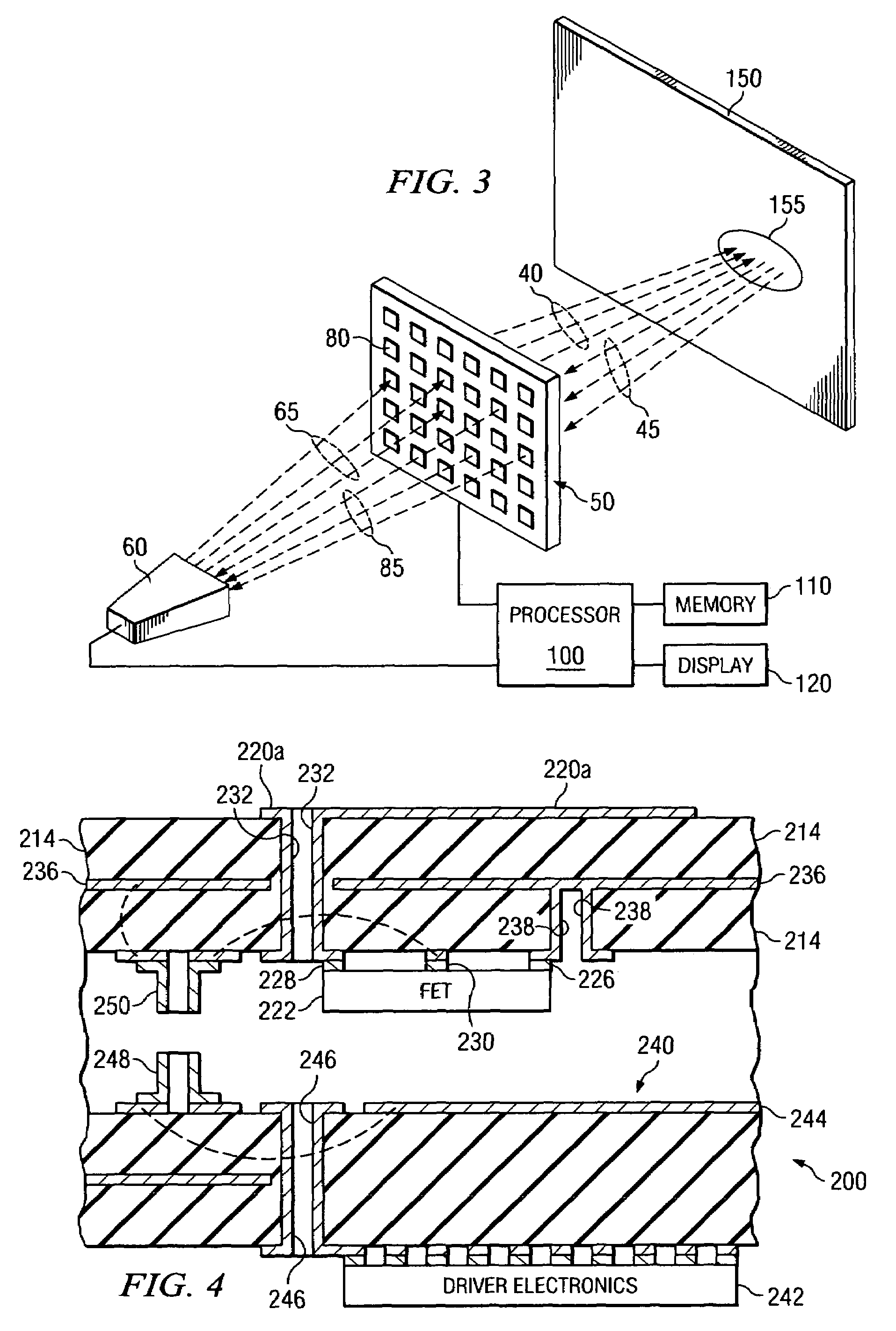
[0026]Referring now to FIG. 1, there is illustrated an exemplary microwave imaging system 10, in accordance with embodiments of the present invention. The microwave imaging system 10 can be used, for example, to provide ongoing surveillance to control a point-of-entry into a structure, monitor passers-by in an area (e.g., a hallway, a...


PUM


Abstract

A microwave imaging system for constructing a stereoscopic microwave image of an object includes an antenna array with a plurality of programmable antenna elements and a processor. Each of the antenna elements is capable of being programmed with a respective first direction coefficient to capture a first microwave image of the object from a first focal point on the array. In addition, each of the antenna elements is capable of being programmed with a respective second direction coefficient to capture a second microwave image of the object from a second focal point on the array. The processor constructs the stereoscopic microwave image from the first and second microwave images.

Description

CROSS-REFERENCE TO RELATED APPLICATIONS[0001]This application is related by subject matter to U.S. application for patent Ser. No. 10 / 997,422, entitled “A Device for Reflecting Electromagnetic Radiation,” U.S. application for patent Ser. No. 10 / 997,583, entitled “Broadband Binary Phased Antenna,” both of which were filed on Nov. 24, 2004, and U.S. Pat. No. 6,965,340, entitled “System and Method for Security Inspection Using Microwave Imaging,” which issued on Nov. 15, 2005.[0002]This application is further related by subject matter to U.S. application for patent Ser. No. 11 / 088,536, entitled “System and Method for Efficient, High-Resolution Microwave Imaging Using Complementary Transmit and Receive Beam Patterns,” U.S. application for patent Ser. No. 11 / 088,831, entitled “System and Method for Inspecting Transportable Items Using Microwave Imaging,” U.S. application for patent Ser. No. 11 / 089,298, entitled “System and Method for Pattern Design in Microwave Programmable Arrays,” U.S....

Claims


Application Information

Patent Timeline
Patent Type & Authority Applications(United States)
IPC IPC(8): G01S13/89G01V3/12G01S7/20
CPCG01S7/20H01Q25/00H01Q3/46G01S13/89
Inventor WEEMS, WILLIAMLEE, GREGORY S.TABER, ROBERT C.CORREDOURA, PAUL L.
Owner AGILENT TECH INC
Why Eureka
Try Eureka