Methods and Apparatus for Timing Synchronization in Packet Networks

a packet network and timing synchronization technology, applied in the direction of electrical apparatus, pulse automatic control, angle demodulation by phase difference detection, etc., can solve the problems of high complexity of methods, high cost of specialized circuits, and affect the accuracy of synchronization, so as to achieve simple and efficient filtering of pdv

Inactive Publication Date: 2008-04-03
AVAGO TECH INT SALES PTE LTD
View PDF3 Cites 49 Cited by
  • Summary
  • Abstract
  • Description
  • Claims
  • Application Information

AI Technical Summary

Benefits of technology

[0006]The present invention provides a two-parameter low pass filter with feedback c

Problems solved by technology

Traditional synchronization methods utilize expensive specialized circuits to provide synchronization signals.
However, due to the store-and-forward operation of packet networks, the synchronization signals or messages will experience an uncertain delay, which will affect the accuracy of synchronization.
This method usually has high complexity.
The process of obtaining satisfactory small delays for calculation is random, therefore, succes

Method used


Image

  • Methods and Apparatus for Timing Synchronization in Packet Networks
  • Methods and Apparatus for Timing Synchronization in Packet Networks
  • Methods and Apparatus for Timing Synchronization in Packet Networks

Examples


Embodiment Construction

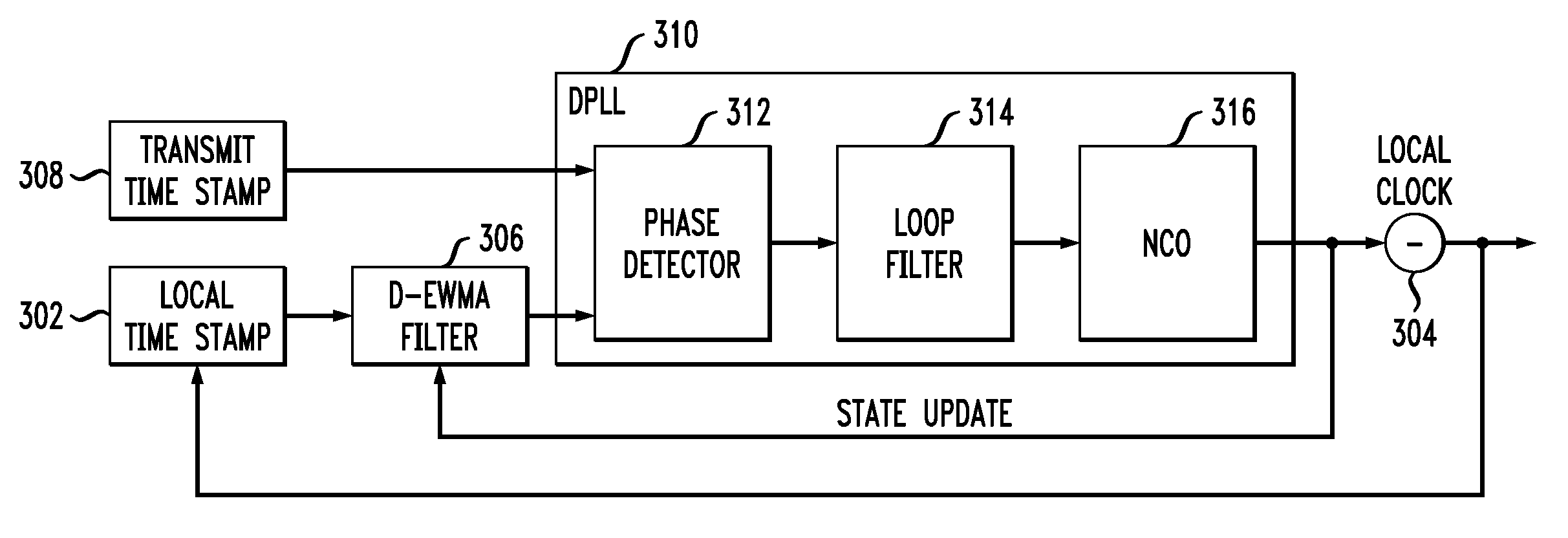
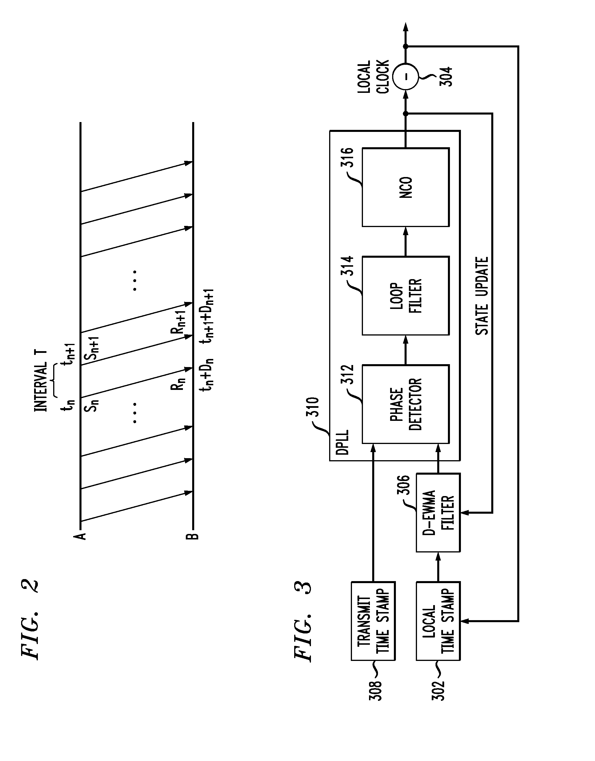
[0018]As will be described in detail below, the present invention in the illustrative embodiment relates generally to the field of packet transfer networks and, more particularly, to improved techniques for the synchronization of a first clock source and a second clock source over packet networks having propagation delay. The illustrative embodiment of the present invention introduces a two-parameter low pass filter with feedback control that provides a simple and efficient way to filter PDV of transferred packets.

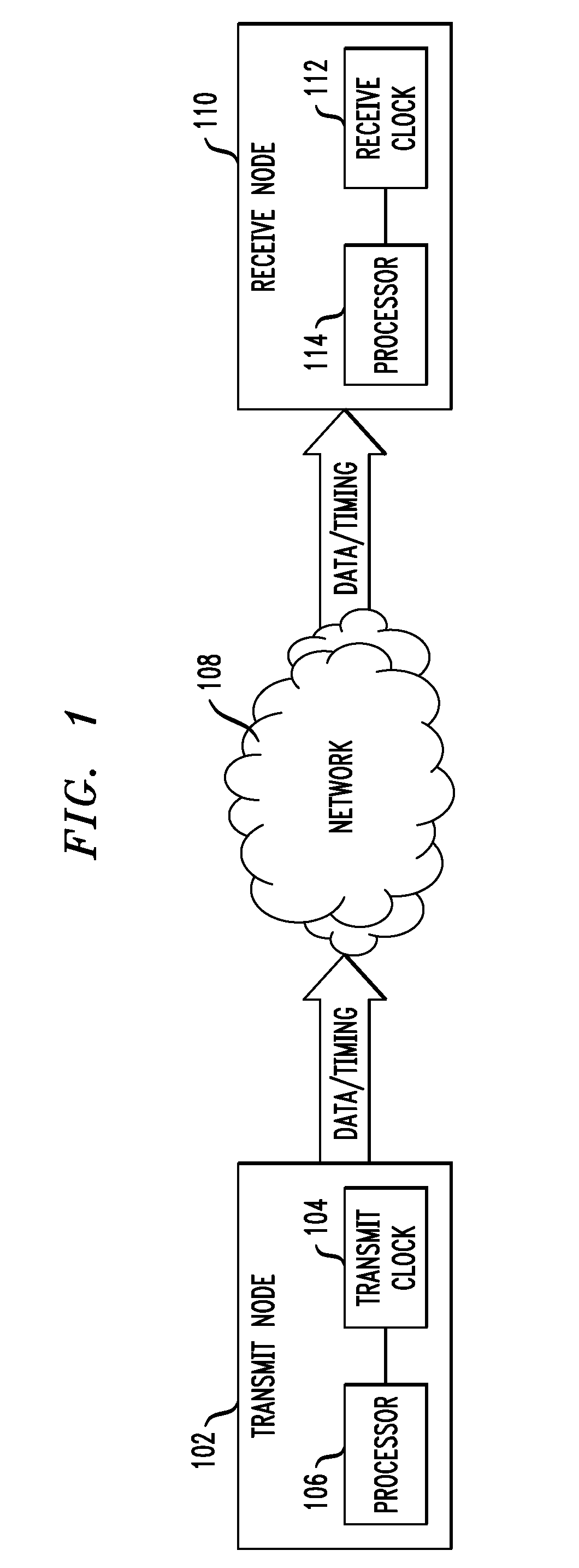
[0019]Referring initially to FIG. 1, a diagram illustrates a packet transfer system, according to an embodiment of the present invention. A transmit node 102 includes a transmit clock 104, or master clock, in communication with a transmit node processor 106. Packets for transfer may be stored in a transfer queue of transmit node and time-stamped at transmit node 102 in accordance with transmit clock 104 and transmit node processor 106. The packets, which include data and t...


PUM


Abstract

Methods and apparatus for synchronizing a first clock of a transmit node and a second clock of a receive node in a packet network are provided. Receive time stamps are generated for transferred packets at a receive node in-accordance with the second clock. Propagation delay variation is filtered from receive time stamp intervals through a filter in accordance with a frequency of the second clock. The filtered receive time stamp intervals and transmit time stamp intervals of the transferred packets are input into a phase locked loop to generate a new frequency for the second clock. The filter and the second clock are updated in accordance with the new frequency for synchronization with the first clock of the transfer node.

Description

FIELD OF THE INVENTION[0001]The present invention relates generally to packet transfer networks and, more particularly, to timing synchronization over packet transfer networks.BACKGROUND OF THE INVENTION[0002]During operation, telecommunication equipment requires timing synchronization for proper communication purposes. Traditional synchronization methods utilize expensive specialized circuits to provide synchronization signals. Currently, with the prevalence of packet networks, such as, for example, Ethernet, cost can be reduced for timing synchronization by transmitting timing synchronization signals between telecommunication equipment within the packet network. However, due to the store-and-forward operation of packet networks, the synchronization signals or messages will experience an uncertain delay, which will affect the accuracy of synchronization. This uncertainty in delay is commonly referred to as packet delay variation (PDV). To improve timing synchronization accuracy, it...

Claims


Application Information

Patent Timeline
IPC IPC(8): H04J3/06
CPCH03L7/08H03L2207/50H04J3/0664
Inventor KATARIA, DEEPAKLI, CHENGZHOU
Owner AVAGO TECH INT SALES PTE LTD
Why Eureka
Try Eureka