
CDMA wireless system

Inactive Publication Date: 2008-04-03
INTEL CORP
View PDF19 Cites 9 Cited by
  • Summary
  • Abstract
  • Description
  • Claims
  • Application Information

AI Technical Summary

Benefits of technology

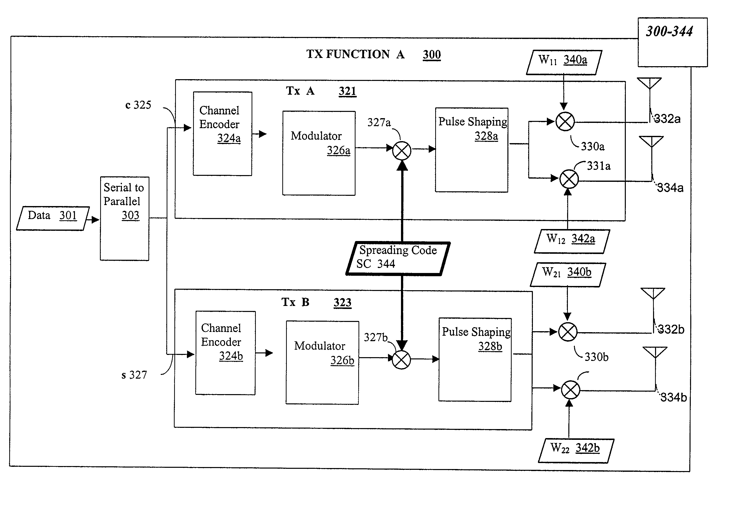
[0015] In this invention, information symbols are transmitted simultaneously on independent streams using the same spreading code but from different transmit antennas at the transmitter. These simultaneous data stream could be intended for the same user (and thereby the data rate for any particular user can be increased) or for different users (thereby increasing the system capacity). Each stream of data can belong to a different signal constellation and use a different channel code. At the receiver, a number of receive antennas equal to at least the number of multiple data streams is used to separate the different data streams. We consider two different cases. The first one when no transmit diversity is used (this case can also include the case when transmit diversity with simple antenna weighting is used) and the second when transmit diversity with space-time block coding is used.

Problems solved by technology

However there is a limit to the number of signals a communication system can accommodate per the number of orthogonal or quasi-orthogonal codes, for a direct sequence spread spectrum application.
This is because the communication system is an interference limited and / or a code limited resource.
However, given the limitation in numbers of code sequences, a wideband system will simply consume the limited number of code resources faster.
However, in a system such as this, the multiple signals must be sufficiently weak to appear as noise when compared to the signal detected after correlating with the specific code sequence.
However, in some cases, many or all of the multipaths provide very weak signals due to interference from other transmitters.
Consequently, this model accomplishes little gain in the data rate.
Capacity is limited by the number of available codes.
However, the number of orthogonal or quasi-orthogonal code sequences is limited for a given code sequence length.
Thus the capacity of the communication system is limited.

Method used


Image

  • CDMA wireless system
  • CDMA wireless system
  • CDMA wireless system

Examples


Embodiment Construction

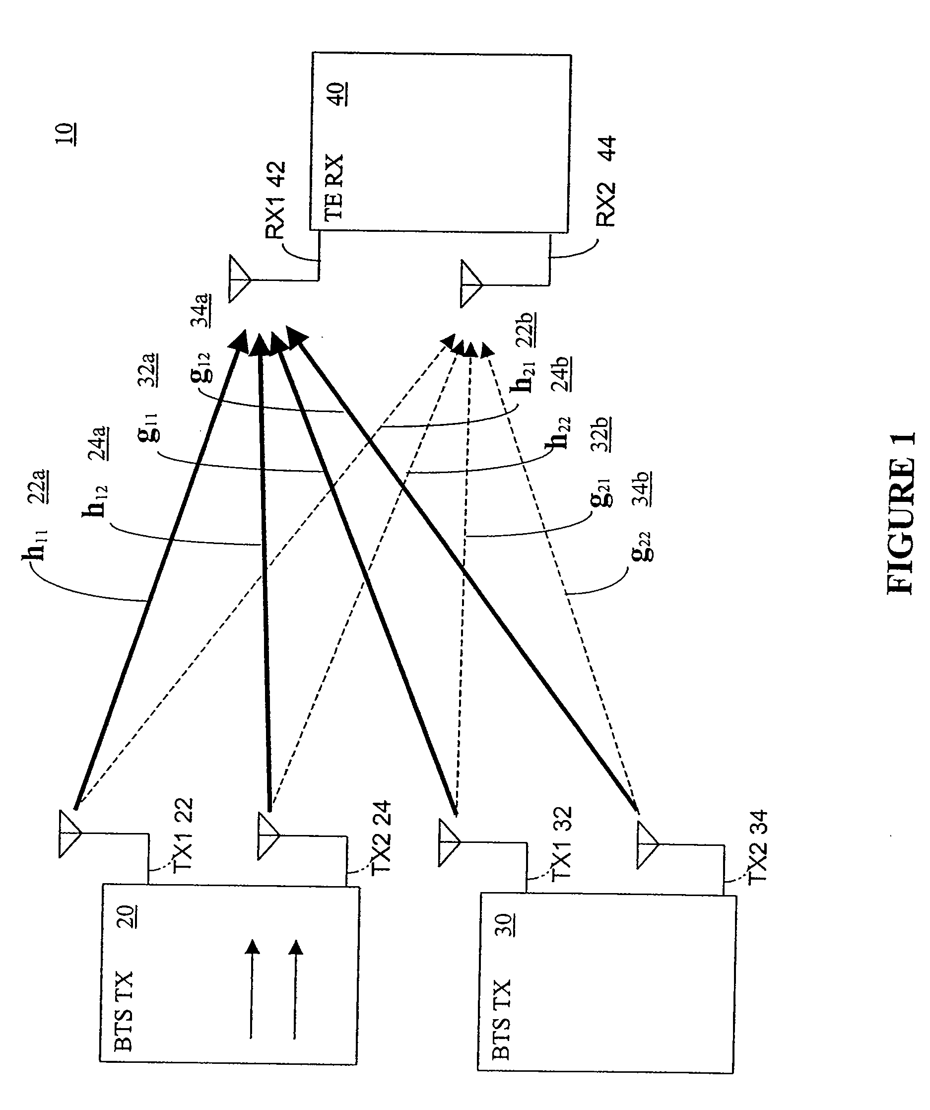
[0034]FIG. 1 is a schematic representation of apparatus 10 for use in practicing the invention. Apparatus 10 comprises at least first and second transmitters 20, 30 and a receiver 40. Transmitter 20 has at least first and second antennas 22, 24 for transmitting signals; and transmitter 30 also has at least first and second antennas 32, 34 for transmitting signals. Receiver 40 has at least first and second antennas 42, 44 for receiving signals. The characteristics of the signal path from the first transmitter to the receiver are represented by the value hij where i identifies the receiver antenna number and j identifies the transmitter antenna number. Similarly, the characteristics of the signal path from the second transmitter to the receiver are represented by the value gij.

[0035] The invention may be practiced using additional antennas and additional transmitters but the number of antennas at the receiver 40 must be equal to at least the number of transmitters.

[0036] As illustra...


PUM


Abstract

Information symbols are transmitted simultaneously on independent streams using the same spreading code but from different transmit antennas at the transmitter. These simultaneous data stream could be intended for the same user (and thereby the data rate for any particular user can be increased) or for different users (thereby increasing the system capacity). Each stream of data can belong to a different signal constellation and use a different channel code. At the receiver, a number of receive antennas equal to at least the number of multiple data streams is used to separate the different data streams. We consider two different cases. The first one when no transmit diversity is used (this case can also include the case when transmit diversity with simple antenna weighting is used) and the second when transmit diversity with space-time block coding is used.

Description

[0001] This application claims priority to the provisional patent application entitled “Time-Space Decoding”, Ser. No. 60 / 322,869, filed Sep. 12, 2001.TECHNICAL FIELD [0002] The present claimed invention relates to the field of communications. In particular, the present claimed invention relate to apparatus and methods for space-time processing and interference suppression techniques that will lead to an increased data rate and or capacity in CDMA based wireless communication systems. BACKGROUND OF INVENTION [0003] Wireless communication systems are ubiquitous for personal and commercial uses. [0004] Demand continue to increase due to increase in quantity of users and increase in quantity of data desired (e.g., graphics, video, data, etc.). However there is a limit to the number of signals a communication system can accommodate per the number of orthogonal or quasi-orthogonal codes, for a direct sequence spread spectrum application. This is because the communication system is an int...

Claims


Application Information

Patent Timeline
IPC IPC(8): H04B1/707H04J99/00H04B1/7107H04B7/02H04B7/06H04L1/06
CPCH04B1/71072H04B7/0615H04B7/0669H04L1/0643H04L1/0618H04L1/0631H04B7/0697
Inventor NAGUIB, AYMAN F.
Owner INTEL CORP
Learn More