Optical transmitter

a technology of optical transmitters and optical receivers, applied in the field of optical transmitters, can solve the problems of not being able to satisfy devices, difficult adjustment, high cost of adjustment systems, etc., and achieve the effect of suppressing the degradation of the quality of transmission signals

Inactive Publication Date: 2008-04-03
FUJITSU LTD
View PDF17 Cites 89 Cited by
  • Summary
  • Abstract
  • Description
  • Claims
  • Application Information

AI Technical Summary

Benefits of technology

[0025]The present invention aims at providing an optical transmitter having the optical modulator control mechanism for preventing the degradation of a signal with accuracy.
[0027]According to the present invention, the shift (level of the drive amplitude), caused by the variance of the electrical signal drive system, the degradation with time, and a temperature change, from the optimum value (vicinity of Vπ) of the drive amplitude in the driver for driving the Mach-Zehnder type modulator can be reduced, and the degradation of the quality of a transmission signal can be suppressed.

Problems solved by technology

However, a measurement unit for monitoring the waveform of the high-speed optical signal is required for the latter, and a resultant adjustment system is costly.
Especially, when the optical transmitter has a plurality of drivers for driving the modulators that are a plurality of Mach-Zehnder type modulators using a differential phase modulator when multivalue modulation such as the RZ-DPSK, the RZ-DQPSK, etc. is used, the adjustment is very hard.
However, there has not been any device for satisfying the above-mentioned requirements.

Method used


Image

  • Optical transmitter
  • Optical transmitter
  • Optical transmitter

Examples


Embodiment Construction

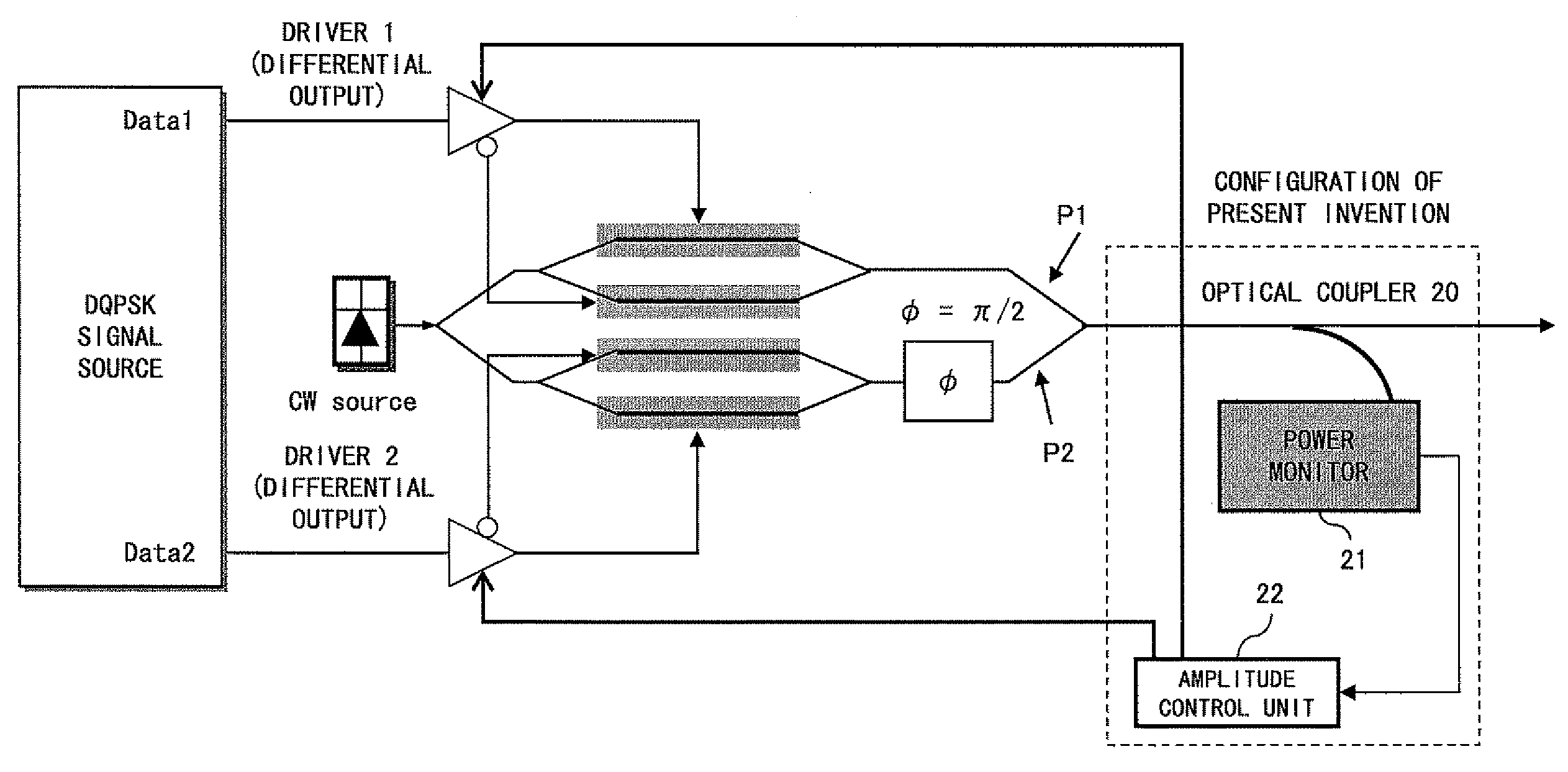
[0059]In the present invention, in an optical transmitter having an optical modulators provided with one or more optical modulation units and a plurality of electric drive circuits for driving the optical modulators, the output amplitude of the drive circuits is feedback-controlled or adjusted such that the optical output power monitored at the output terminal of the optical transmitter can be the maximum.

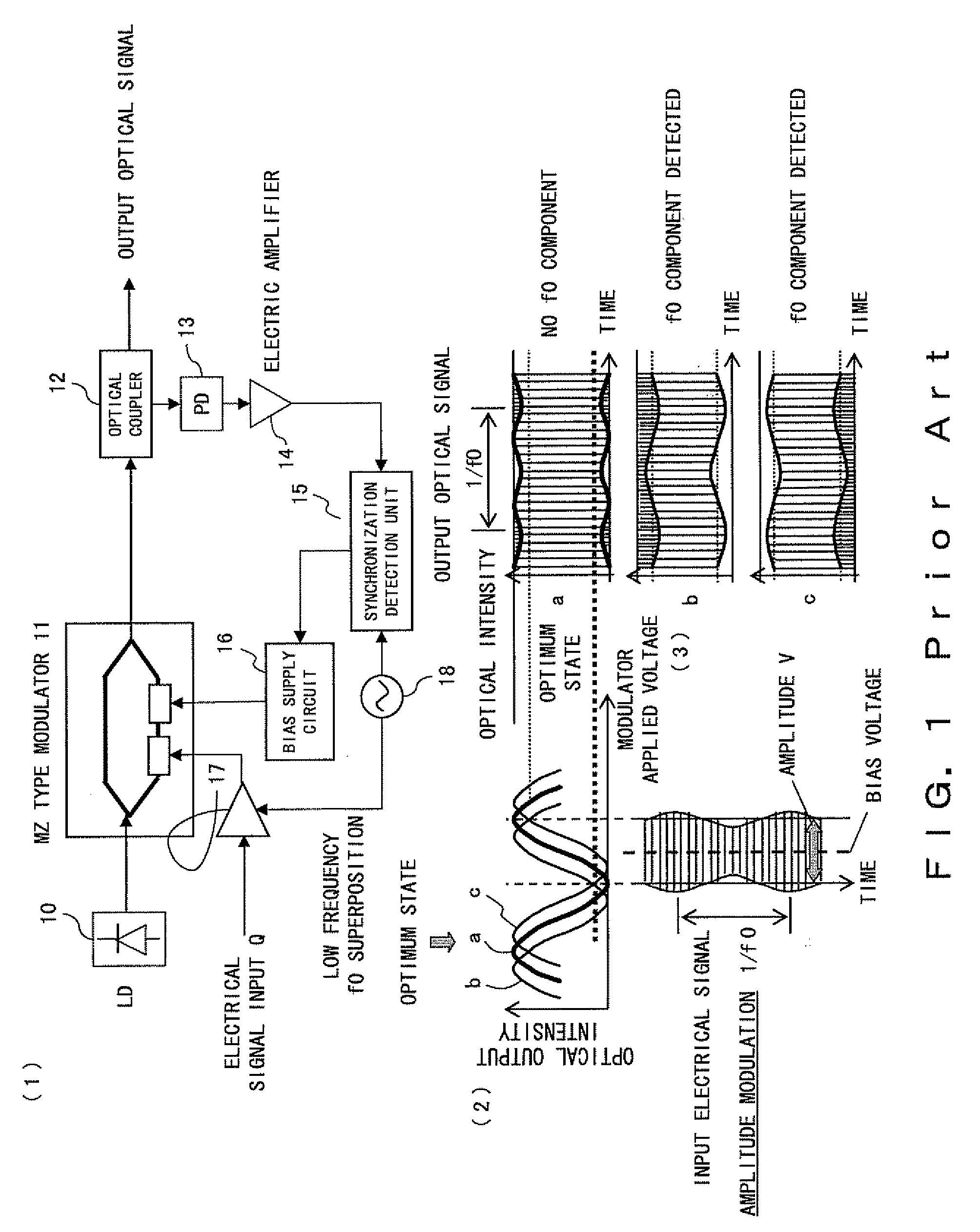
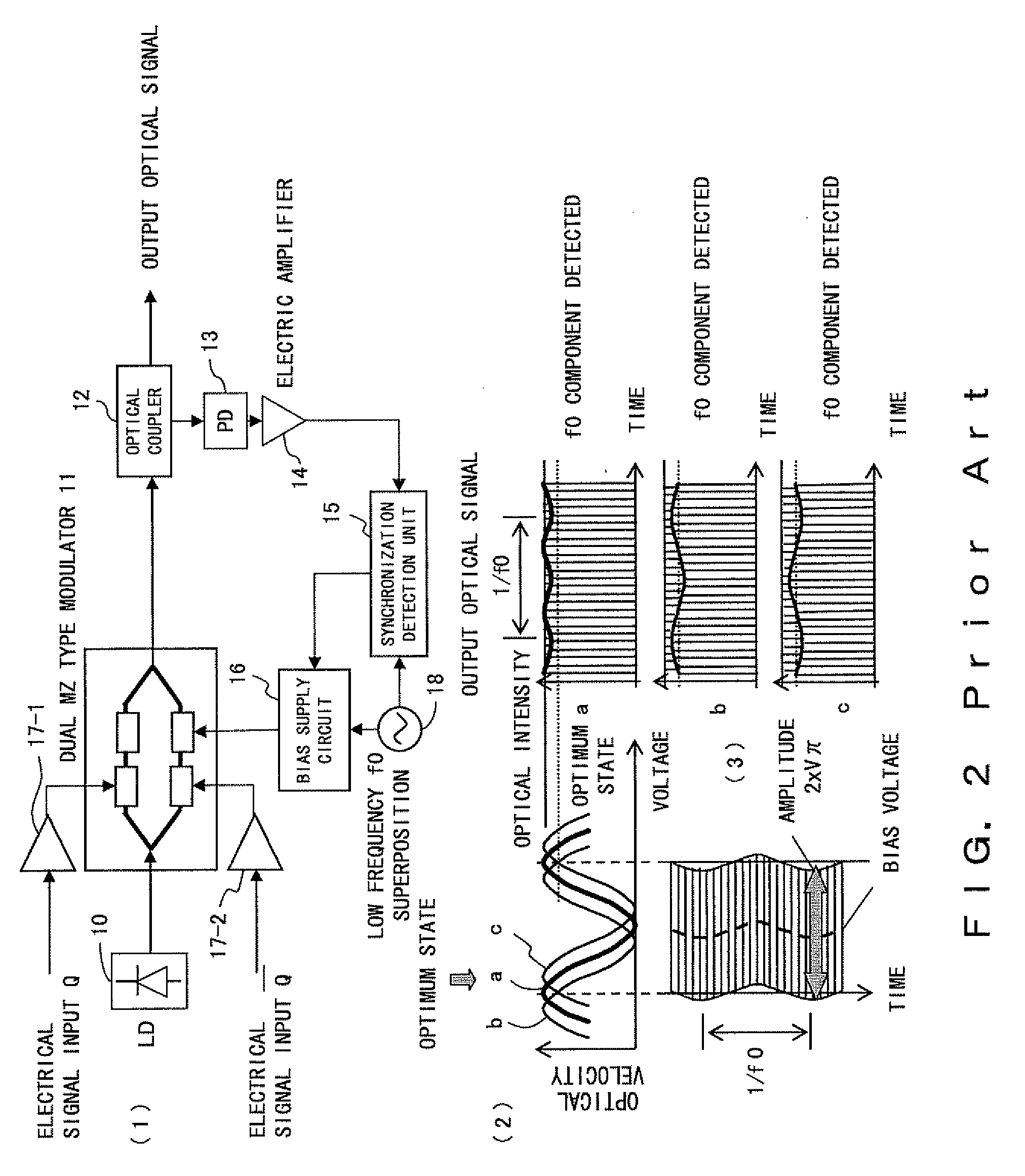
[0060]Otherwise, in an optical transmitter having an optical modulators provided with one or more optical modulation units and a plurality of electric drive circuits for driving the optical modulators, the electric drive signal amplitude corresponding to the modulation system for detecting a change in monitor signal component using a low frequency pilot signal and performing modulation with the electric drive signal amplitude corresponding to 2×Vπ of peak, valley, and peak in the bias-to-optical-intensity characteristic of the Mach-Zehnder type LN modulator, and the modulation syst...


PUM


Abstract

A signal Data1 and Data2 are output from a DQPSK signal source. The output signal is input to the modulator drivers 1 and 2 of the differential output. A drive signal is applied from the drivers 1 and 2 to a modulator, and modulated light is output. An optical coupler 20 branches modulator output, and a power monitor 21 detects the power of the branched light. A detection result is transmitted to an amplitude control unit 22. The amplitude control unit 22 adjusts the amplitude of the drivers 1 and 2 such that the detection result of the power monitor 21 can be the maximum.

Description

BACKGROUND OF THE INVENTION[0001]1. Field of the Invention[0002]The present invention relates to an optical transmitter in an optical communication system.[0003]2. Description of the Related Art[0004]Recently, with an increasing demand for a 40 Gbit / s next-generation optical transmission system, a transmission distance and frequency use efficiency equivalent to a 10 Gbit / s system are demanded. As realizing means, various systems (duobinary, CS-RZ (carrier suppression-return to zero), DPSK (differential phase shift keying), DQPSK (differential quadrature phase-shift keying), etc.) that excel the NRZ modulation system (non return to zero) conventionally applied in the system of 10 Gb / s or less in frequency use efficiency, resistance to optical-signal-to-noise ratio, and resistance to nonlinearity have been studied actively.[0005]Especially, the DQPSK modulation system simultaneously transmits two phase-modulated digital signals using optical light of one frequency. In this system, the...

Claims


Application Information

Patent Timeline
Patent Type & Authority Applications(United States)
IPC IPC(8): H04B10/04H04B10/07H04B10/2507H04B10/2513H04B10/516H04B10/548H04B10/58H04B10/61H04L27/20
CPCH04B10/505H04B10/564H04B10/50575H04B10/50572
Inventor TANAKA, TOSHIKIHOSHIDA, TAKESHINAKASHIMA, HISAOAKIYAMA, YUICHI
Owner FUJITSU LTD
Why Eureka
Try Eureka