Airfoil cooling circuits and method

a technology of airfoil and cooling circuit, which is applied in the direction of liquid fuel engines, foundry patterns, moulding apparatus, etc., can solve the problems of insufficient flexibility to effectively and efficiently control the temperature of the pressure sidewall and the suction sidewall

Inactive Publication Date: 2008-04-03
GENERAL ELECTRIC CO
View PDF9 Cites 111 Cited by
  • Summary
  • Abstract
  • Description
  • Claims
  • Application Information

AI Technical Summary

Problems solved by technology

This presents the challenge of making the core sturdy enough to survive the pouring of the metal while maintaining the stringent requirements for positioning the core.
This design

Method used


Image

  • Airfoil cooling circuits and method
  • Airfoil cooling circuits and method
  • Airfoil cooling circuits and method

Examples


Embodiment Construction

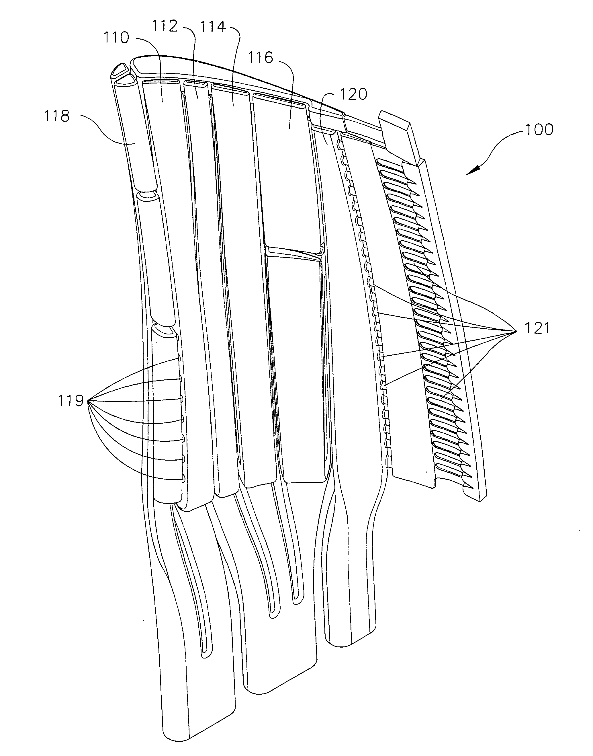
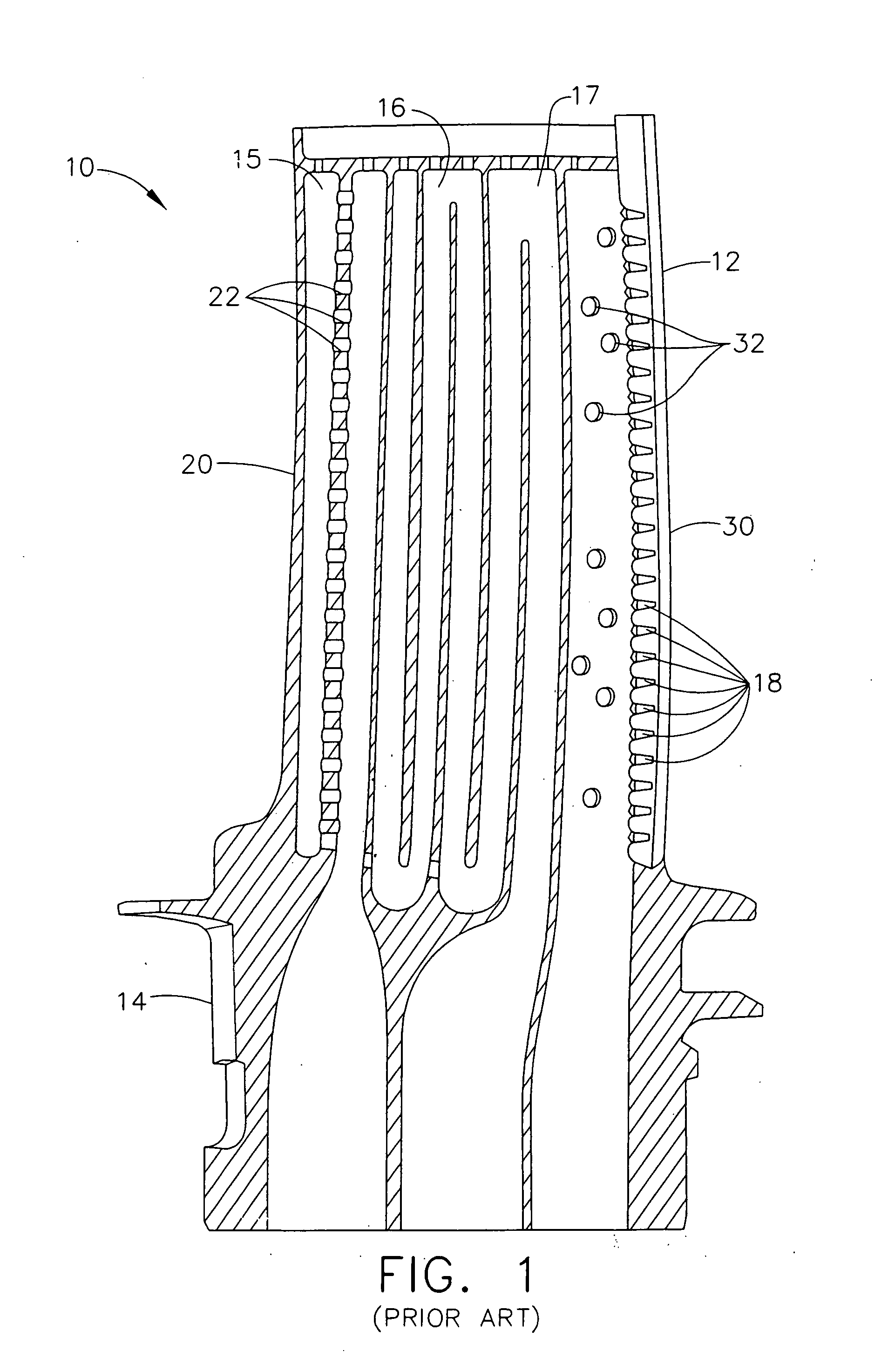
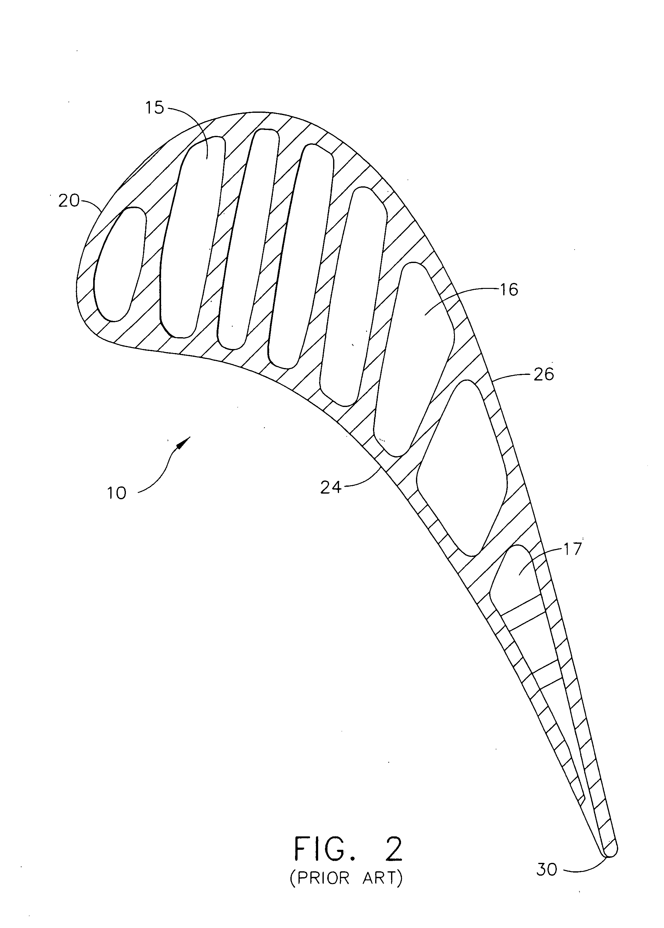
[0018]Referring now specifically to the drawings, prior art airfoils incorporating internal cooling circuits are shown in FIGS. 1-4. FIGS. 1 and 2 illustrate a conventional prior art turbine blade 10 for a gas turbine engine. The blade 10 includes an airfoil section 12 and a root 14 that is attached with other blades 10 to a rotatable turbine hub, not shown, and projects outwardly from the hub into a flowpath from the engine's combustion chamber. Blade 10 includes three cooling circuits—a leading edge circuit 15, a mid chord circuit 16, and a trailing edge circuit 17. The leading edge circuit 15 is an impingement-type circuit whereby the leading edge 20 is cooled through impingement of air through holes 22 on the interior of the leading edge 20.

[0019]The mid chord circuit 16 is an axial serpentine-type circuit. In this design, the pressure sidewall 24 and the suction sidewall 26 are cooled by contact with the same air at the same temperature. This design is easy to cast, but does no...


PUM

PropertyMeasurementUnit
Angleaaaaaaaaaa
Pressureaaaaaaaaaa
Flow rateaaaaaaaaaa

Abstract

An airfoil is disclosed having at least first and second cast, axially-stacked internal airflow cooling circuits. Each circuit defines multiple air flow passages positioned laterally between a pressure sidewall side and a suction sidewall side of respective ones of the circuits. Each of the circuits is formed by a separate casting core. Methods of forming a axially-stacked core and an airfoil are also disclosed.

Description

GOVERNMENT INTERESTS[0001]This invention was made with government support under PRDA-7 government contract No. F33615-C-2212 awarded by the Department of Defense. The government has certain rights to this invention.TECHNICAL FIELD AND BACKGROUND OF THE INVENTION[0002]This invention relates generally to gas turbine engines, and more particularly to internally cooled airfoils used in gas turbine engines.[0003]Gas turbine engines, such as aircraft jet engines, include many components (e.g., turbines, compressors, fans and the like) that utilize airfoils. Turbine airfoils, such as turbine blades and nozzle vanes are exposed to the highest operating temperatures and thus typically employ internal cooling to keep the airfoil temperatures within specified design limits. The design limits define an acceptable balance between factors such as operating efficiency, wear longevity and heat tolerance.[0004]A turbine rotor blade, for example, has a shank portion that is attached to a rotating tur...

Claims


Application Information

Patent Timeline
IPC IPC(8): F01D5/18
CPCB22C9/043F01D5/18Y10T29/49243F05D2230/21Y10T29/49245Y02T50/676Y02T50/60
Inventor BRASSFIELD, STEVEN ROBERTLEE, CHING-PANGDOUGHTY, ROGER LEEJENDRIX, RICHARD WILLIAMWILLIAMS, CORY MICHAEL
Owner GENERAL ELECTRIC CO
Why Eureka
Try Eureka