
Unified communication repeater

a repeater and unified technology, applied in the field of wireless communication, can solve the problems of increasing load, generating oscillation, increasing noise of reverse entry, etc., and achieve the effect of preventing precisely and stably the generation of oscillation

Inactive Publication Date: 2008-04-03
WIRELESS DATA COMM
View PDF5 Cites 79 Cited by
  • Summary
  • Abstract
  • Description
  • Claims
  • Application Information

AI Technical Summary

Benefits of technology

[0020]An object of the present invention is to provide a unified communication repeater for precisely and stably preventing oscillation generated during the bidirectional repeating of signals.
[0021]Another object of the present invention is to provide a unified communication repeater for minimizing radiation patterns serving as signal interference between a receiver antenna and a transmitter antenna for the bidirectional signal repeating.

Problems solved by technology

However, since circumstance of the wireless communication service is too unstable, a shadow area where radio waves cannot arrive still exists
However, due to the increase of the repeaters, reversely entering noise is also increased, and oscillation is generated according to the installation place or the installation circumstance of the repeaters.
Particularly, since the oscillation is applied to the signals as noise, load is increased and the quality of the signals is deteriorated.
As a result, signal interference occurs between the receiver antenna and the transmitter antenna.
For this reason, there is a difficulty in installing the antennas.

Method used


Image

  • Unified communication repeater
  • Unified communication repeater
  • Unified communication repeater

Examples


first embodiment

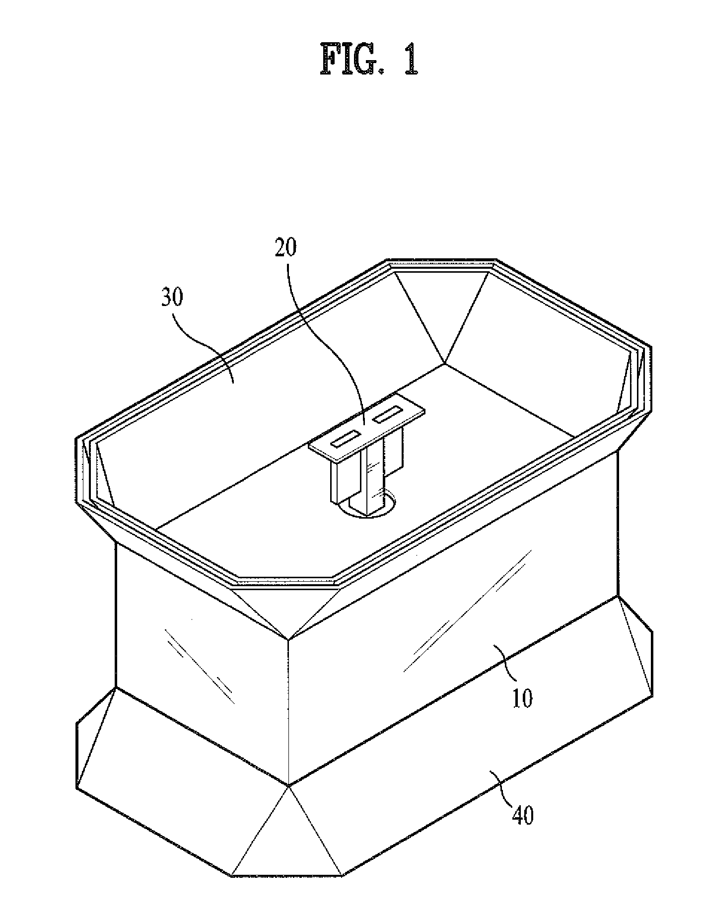
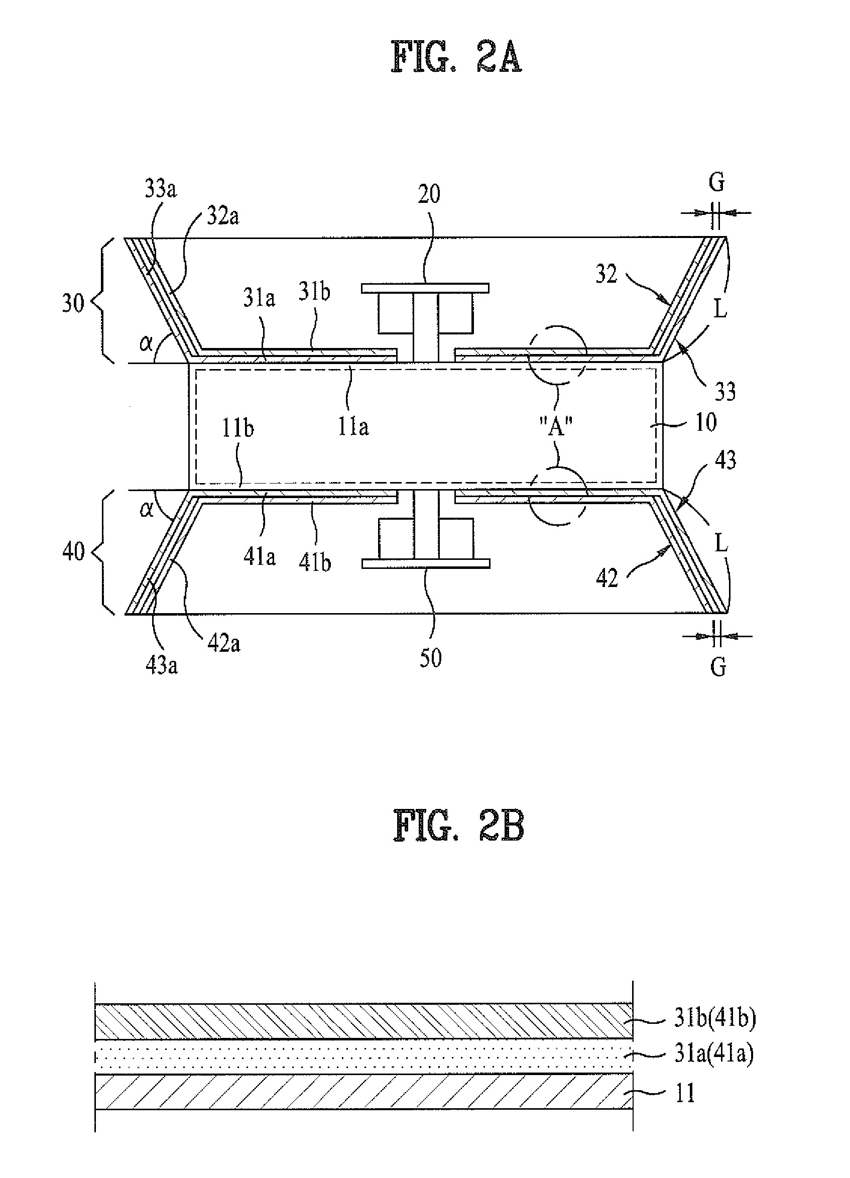
[0050]FIGS. 2a and 2b are respectively a sectional view and a partial detail view illustrating a communication repeater according to the present invention, namely, detail views of the repeater in FIG. 1.

second embodiment

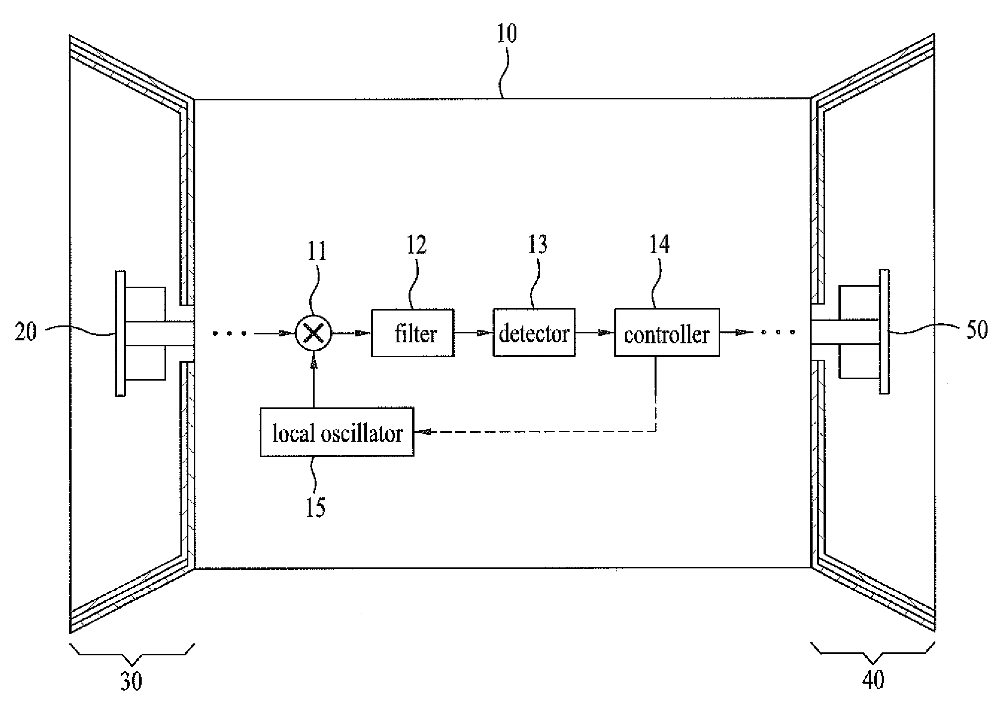
[0051]FIG. 3 is a view illustrating configuration of a communication repeater according to the present invention.

[0052]The unified communication repeaters in FIGS. 1 to 3 include repeater circuits installed to repeat the downlink signals and the uplink signals between the network and the terminals.

[0053]Configuration of the repeater circuit is illustrated in FIG. 4, and the unified communication repeater of the present invention includes a housing 10 for protecting the repeater circuit.

[0054]The housing 10 shields the repeater circuit. The housing 10 is electrically grounded.

[0055]Antennas for the bidirectional transmission and reception of signals are attached to opposite sides of the housing 10.

[0056]The antennas are distinguished as a first antenna for transmitting and receiving signals between the unified communication repeater and the network and a second antenna for transmitting and receiving signals between the unified communication repeater and the terminals.

[0057]The first ...


PUM


Abstract

A unified communication repeater for wireless communication repeats signals between a network and communication terminals via a wireless line. The unified communication repeater precisely and stably prevents oscillation generation during bidirectional signal repeating, and minimizes radiation patterns serving as signal interference between a receiver antenna and a transmitter antenna for the bidirectional signal repeating.

Description

BACKGROUND OF THE INVENTION[0001]1. Field of the Invention[0002]The present invention relates to wireless communication, and more particularly, to a unified communication repeater for repeating signals between a network and a communication terminal via a wireless line.[0003]2. Discussion of the Related Art[0004]Due to development of communication technology, a variety of wireless communication services are provided via a wireless line.[0005]Recently, as the number of wireless communication service subscribers is increased, the number of stations is remarkably increased to provide sufficient wireless communication service.[0006]However, since circumstance of the wireless communication service is too unstable, a shadow area where radio waves cannot arrive still exists[0007]Success of wireless communication provider is dependent upon whether the shadow area is effectively removed with low costs or not.[0008]Meanwhile, the most effective method of removing the shadow area is to use a re...

Claims


Application Information

Patent Timeline
IPC IPC(8): H04B7/15
CPCH04B7/15564H04B7/14H04B1/59
Inventor KONG, SUNG HOKANG, GI CHO
Owner WIRELESS DATA COMM
Learn More