Passive throttling valve outside of muffler

Inactive Publication Date: 2008-04-10
ARVIN TECH INC
View PDF8 Cites 27 Cited by
  • Summary
  • Abstract
  • Description
  • Claims
  • Application Information

AI Technical Summary

Benefits of technology

[0005]In one particular example, the valve is mounted within a section of the exhaust tube having a reduced cross-sectional area and is pivotable into a larger cross-sectional area section of the exhaust tube to avoid interference with tube walls and provide a relatively large range of movement.

Problems solved by technology

Although effective, mufflers are often relatively large in size and provide limited nose attenuation.
However, the proposed valves have numerous drawbacks that limit widespread use.
For example, the temperature of the hot exhaust gas is approximately 1000° C., and therefore the valve requires actuation mechanisms that utilize special materials, that are relatively expensive, to withstand the severe temperatures.
Moreover, since the valves are located within the exhaust tubes, they obstruct the flow of the exhaust gases and thereby limit effectiveness of the valve for noise attenuation.

Method used


Image

  • Passive throttling valve outside of muffler
  • Passive throttling valve outside of muffler
  • Passive throttling valve outside of muffler

Examples


Embodiment Construction

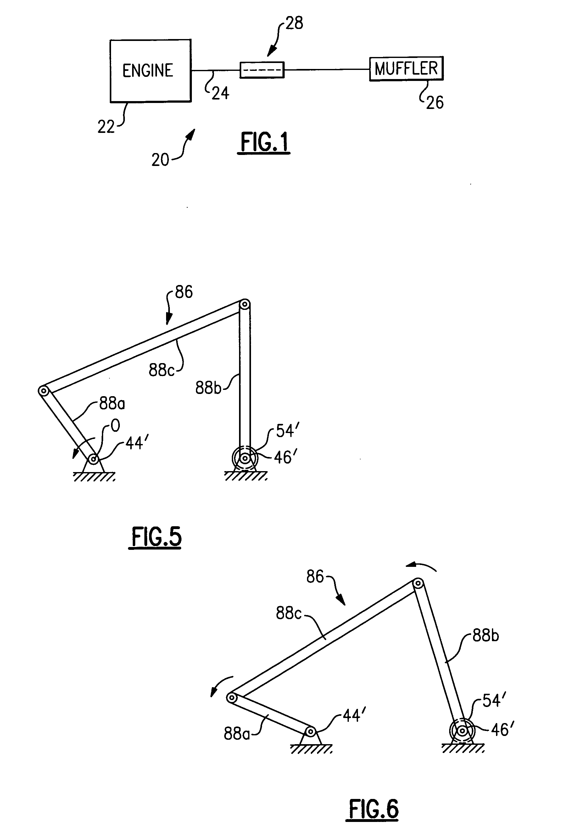
[0015]FIG. 1 schematically illustrates selected portions of an example exhaust system 20. In this example, the exhaust system 20 includes an engine 22, such as a gas combustion engine for use in a vehicle. The engine 22 is connected to one or more exhaust tubes 24 for conveying hot exhaust gases from the engine 22 to a muffler 26. A noise attenuation device 28 is associated with the exhaust tube 24 for reducing sound carried by the exhaust gases. Although, the illustrated example includes the muffler 26, the noise attenuation device 28 can be used without the muffler 26, or instead of the muffler 26.

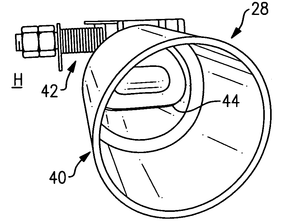
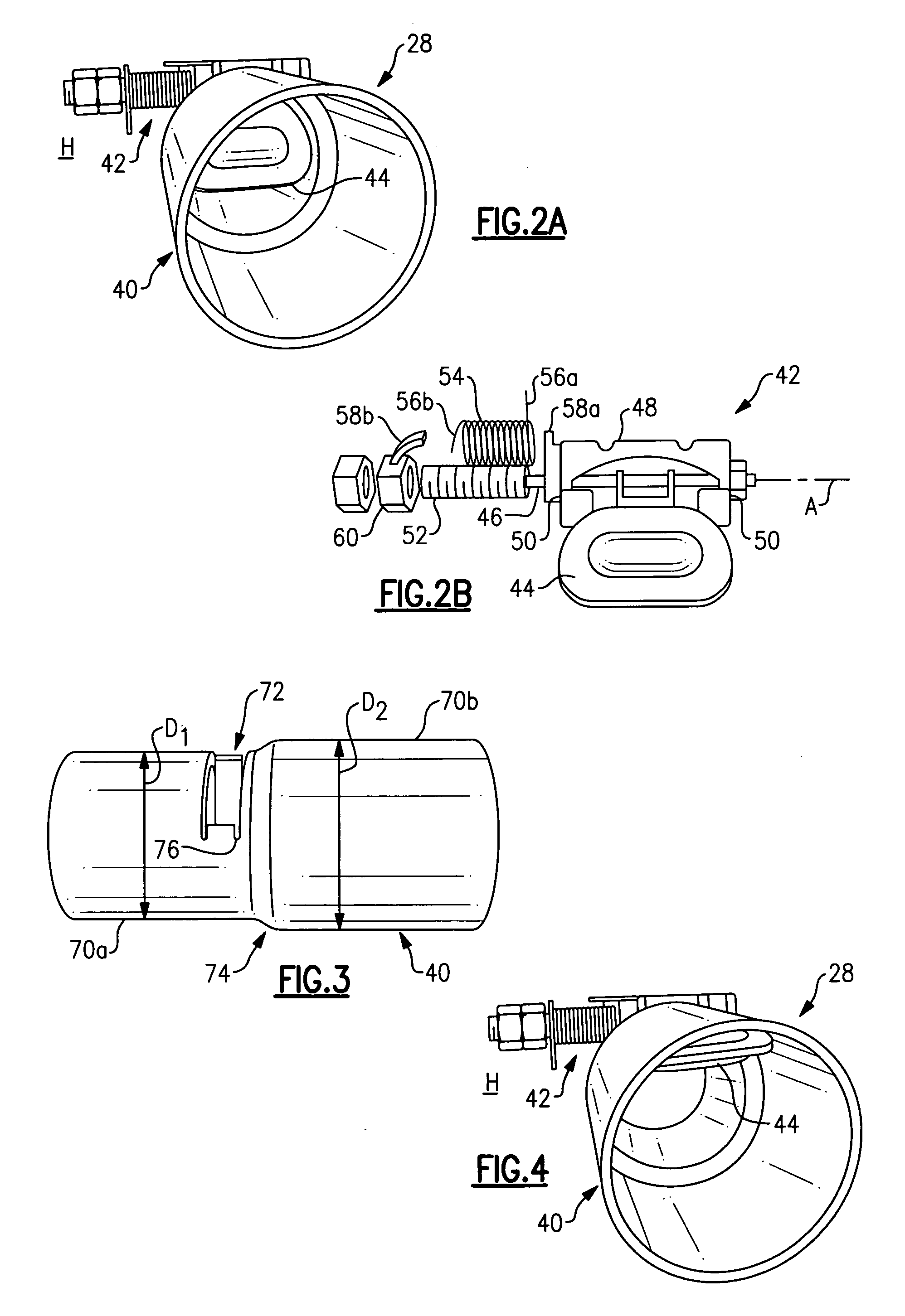
[0016]FIG. 2A illustrates a perspective view of one example noise attenuation device 28. In this example, the noise attenuation device 28 includes an exhaust tube section 40 connected to the exhaust tube 24 from the engine 22 for conveying the heated exhaust gases. A valve 42 is disposed at least partially within the exhaust tube section 40 to attenuate noise carried by the exhaust gases...


PUM


Abstract

An exhaust system includes an exhaust tube for conveying a heated exhaust flow from an engine. A valve is mounted at least partially within the exhaust tube for noise attenuation. The valve includes a bias member mounted outside of the engine exhaust tube within a heat transfer environment to maintain the bias member at a low temperature. The bias member biases the valve against the heat exhaust flow toward a predetermined position. The valve is mounted within a section of the tube having a smaller cross-sectional area and pivots into a larger cross-sectional area section of the exhaust tube to avoid interference with tube walls and provide a relatively large range of movement.

Description

BACKGROUND OF THE INVENTION[0001]This invention relates to vehicle exhaust systems and, more particularly, to a passive noise attenuation valve for use with an exhaust tube of the vehicle exhaust system.[0002]Exhaust systems are widely known and used with combustion engines. Typically, the exhaust system includes exhaust tubes that convey hot exhaust gases from the engine to a muffler. The muffler includes acoustic chambers that cancel out sound waves carried by the exhaust gases. Although effective, mufflers are often relatively large in size and provide limited nose attenuation.[0003]It has been proposed to utilize a valve within the exhaust tubes to provide noise attenuation. However, the proposed valves have numerous drawbacks that limit widespread use. For example, the temperature of the hot exhaust gas is approximately 1000° C., and therefore the valve requires actuation mechanisms that utilize special materials, that are relatively expensive, to withstand the severe temperatu...

Claims


Application Information

Patent Timeline
IPC IPC(8): F01N7/00
CPCF01N1/165
Inventor ABRAM, KWINCALLAHAN, JOSEPHWILLATS, ROBIN
Owner ARVIN TECH INC
Why Eureka
Try Eureka