Air conditioning apparatus for vehicle

a technology for air conditioning apparatus and vehicle, which is applied in the direction of domestic cooling apparatus, lighting and heating apparatus, and machine operation mode, etc., can solve the problems of uneven distribution of flow speed and inability to uniformly heat conditioned air in the right and left direction of the vehicl

Inactive Publication Date: 2008-04-10
DENSO CORP
View PDF9 Cites 15 Cited by
  • Summary
  • Abstract
  • Description
  • Claims
  • Application Information

AI Technical Summary

Benefits of technology

[0011]Accordingly, the volumes of air flowing into the first passages are substantially uniform. As such, at the position downstream of the baffle member, unevenness of temperature of mixed air of the bypass air and the heated air with respect to the alignment direction is reduced. Accordingly, temperatures of airs passing through the openings are substantially uniform.

Problems solved by technology

Therefore, the mixed air passes through the air-blowing openings from the air mixing chamber and is blown into the passenger compartment, while having the uneven distribution of the flow speed.
As a result, the temperature of the conditioned air is not uniform in the vehicle right and left direction due to the uneven distribution of the flow speed.

Method used


Image

  • Air conditioning apparatus for vehicle
  • Air conditioning apparatus for vehicle
  • Air conditioning apparatus for vehicle

Examples


first embodiment

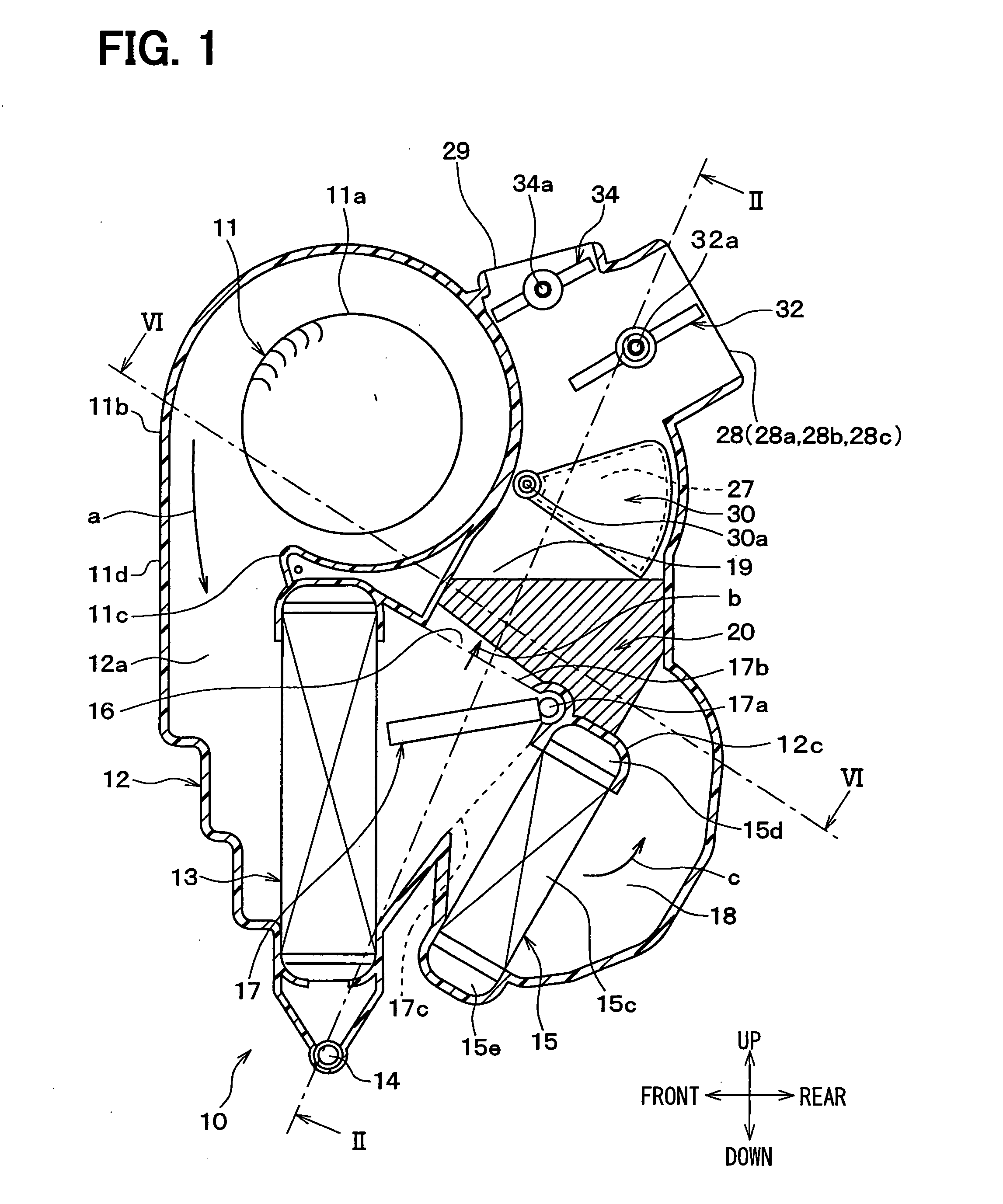
[0019]A first embodiment of the present invention will be described with reference to FIGS. 1 to 3. Referring to FIG. 1, an interior unit 10 of a vehicular air conditioning apparatus is mounted in a space defined in an instrument panel that is located at a front part of a passenger compartment of a vehicle, and at a substantially middle position with respect to a vehicle right and left direction. In the drawings, an up and down arrow and a front and rear arrow denote respective directions when the interior unit 10 is mounted in a vehicle. In FIG. 1, a direction perpendicular to a paper of FIG. 1 corresponds to a right and left direction of the vehicle (H1 in FIG. 2).

[0020]The interior unit 10 has a blower 11 at a front upper position. The blower 11 includes a fan 11a, a motor (not shown) for driving the fan 11a, and a scroll casing 11b. For example, the fan 11a is a centrifugal multi blade fan, such as a sirocco fan. The scroll casing 11b houses the fan 11a and forms a scroll passag...

second embodiment

[0082]A second embodiment will be described with reference to FIG. 4. In the first embodiment, the example in which the flow speed of the upstream cooled air is higher at the middle portion than at the right and left ends is described. On the other hand, in the second embodiment, an example in which the flow speed of the upstream cooled air is lower at the middle portion than at the right and left ends will be described.

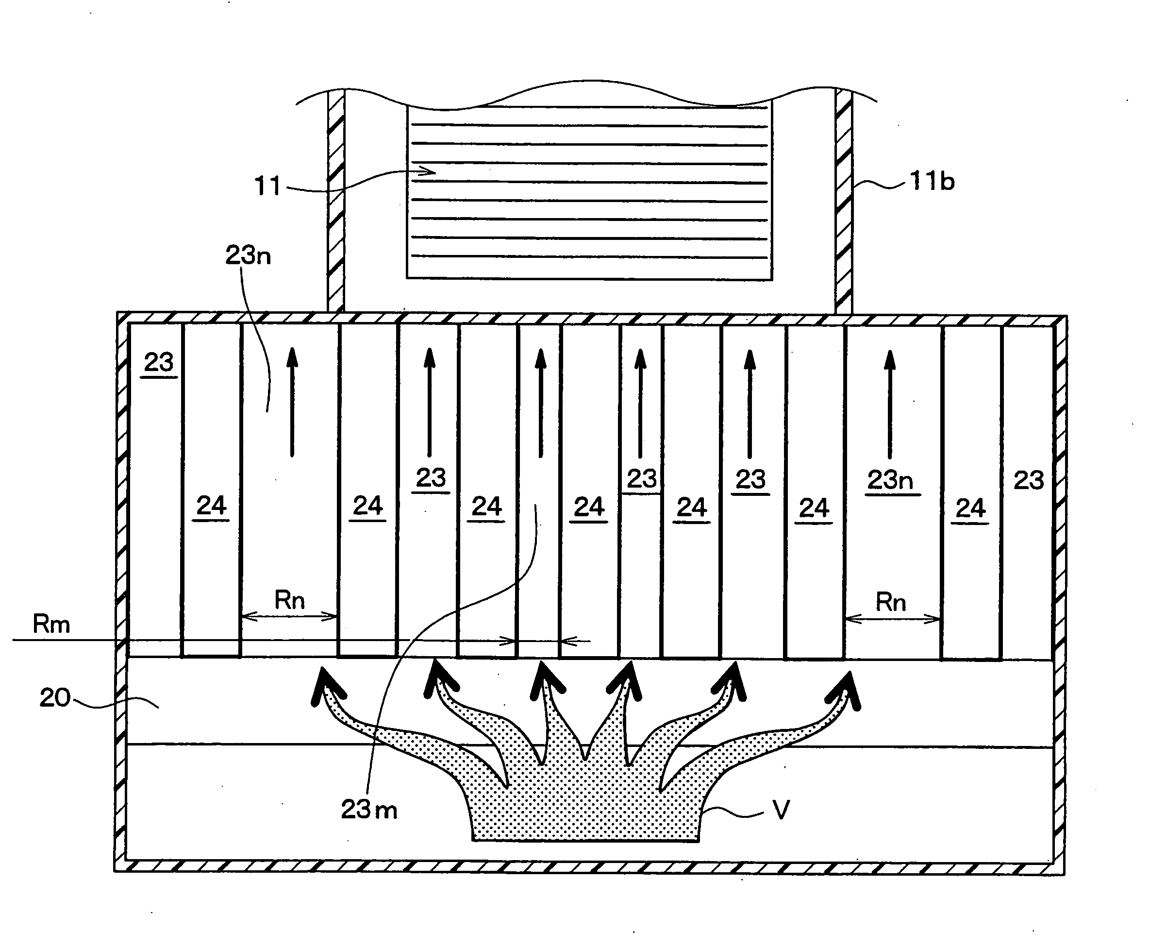
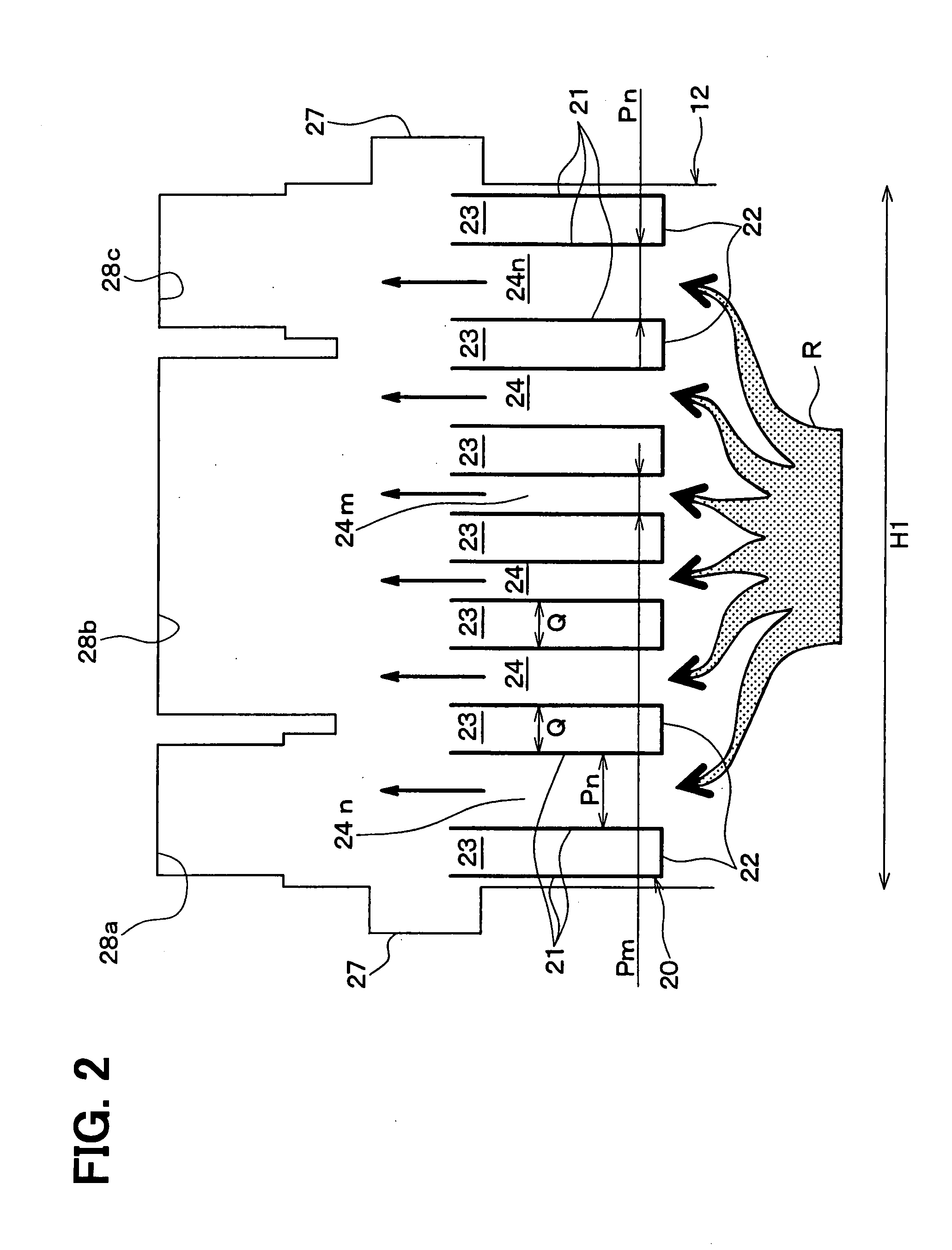
[0083]In an example shown in FIG. 4, the baffle member 20 has the six cooled air main-flow passages 24 (24m, 24n). The cooled air main-flow passages 24n, which are located closer to the side walls of the unit case, 12, that is, located at positions corresponding to a relatively high flow speed, have the width Pn. The cooled air main-flow passages 24m, which are located at positions corresponding to a relatively low flow speed, have the width Pm. The width Pn of the side cooled air-main-flow passages 24n is smaller than the width Pm of the middle main-flow passages 24...

third embodiment

[0085]A third embodiment will be described with reference to FIG. 5. In the first embodiment, the example in which the flow speed of the upstream cooled air is higher at the middle portion than the right and left ends is described. On the other hand, in the third embodiment, an example in which the flow speed of the upstream cooled air is higher at one of the right and left ends than the other end will be described.

[0086]In the example shown in FIG. 5, the flow speed of the upstream cooled air is higher at the left end than at the right end. In this case, left cooled air main-flow passages 24m, which are located on a left side where the flow speed of the upstream cooled air is relatively high, has a width Pm. Right cooled air main-flow passages 24n, which are located on a right side on which the flow speed of the cooled air is relatively low, has a width Pn. The width Pn is larger than the width Pm.

[0087]Therefore, a part of the upstream cooled air separates from the left side towar...


PUM


Abstract

An air conditioning apparatus for a vehicle has a unit case, a heat exchanger for generating a heated air, a bypass passage through which a bypass air flows while bypassing the heat exchanger, and a baffle member having first passages and second passages. The unit case has openings for introducing a conditioned air into a passenger compartment. The openings are aligned in an alignment direction across a width of the unit case. The first passages and second passages are alternately arranged in the alignment direction. One of the bypass air and the heated air has an uneven distribution of a flow speed in the alignment direction at a position upstream of the baffle member, and flows in the first passages. Widths of the first passages are varied according to the distribution of the flow speed.

Description

CROSS REFERENCE TO RELATED APPLICATION[0001]This application is based on Japanese Patent Application No. 2006-276387 fired on Oct. 10, 2006, the disclosure of which is incorporated herein by reference.FIELD OF THE INVENTION[0002]The present invention relates to a vehicular air conditioning apparatus of an air mixing type.BACKGROUND OF THE INVENTION[0003]For example, a vehicular air conditioning apparatus of an air mixing type has an evaporator for cooling air blown by a blower, a heater core for heating air cooled by the evaporator, a bypass passage through which the cooled air flows to bypass the heater core, and an air mixing door, within a unit case. The air mixing door is operable to adjust a ratio of the volume of the cooled air passing through the bypass passage to the volume of the heated air passing through the heater core, thereby to control a temperature of air to be blown into a passenger compartment of a vehicle. Hereafter, the air, the temperature of which is controlled...

Claims


Application Information

Patent Timeline
Patent Type & Authority Applications(United States)
IPC IPC(8): B60H1/32
CPCB60H2001/00092B60H1/00064
Inventor NAGATA, KYOKOUEMURA, YUKIO
Owner DENSO CORP
Why Eureka
Try Eureka