Cosmetic applicators and methods of manufacture

a technology of cosmetics and applicators, applied in the field of cosmetics applications, can solve the problems of limited number of suppliers, relative cost, limited variety of possible configurations of twisted-in-wire brushes, etc., and achieve the effect of facilitating the separation of molded objects

Inactive Publication Date: 2008-04-10
ALBEA SERVICES SAS
View PDF3 Cites 88 Cited by
  • Summary
  • Abstract
  • Description
  • Claims
  • Application Information

AI Technical Summary

Benefits of technology

[0008] The terms “mold plane” and “pull direction” are used herein with reference to conventional types of molds, such as injection molds, for producing plastic articles, characterized in having relatively movable shaped mold surfaces that face each other on opposite sides of a notional plane (“mold plane”) and, in the course of a molding operation, move relatively toward and away from each other in a direction (“pull direction”) perpendicular to the plane. When the mold plates are brought together, the respective shaped mold surfaces meet and cooperatively define a volume that is filled with plastic material, thereby to mold the material into an article having the configuration of the defined volume. The initial substantially planar configuration of the panel and the initial substantially parallel pull-direction orientation of the features formed therein or thereon, in the applicators of the invention, facilitates separation of the molded article from the applicator, while the subsequent bending of the panel around a longitudinal axis transforms the article into an applicator having, e.g., a generally cylindrical or conical core with features exemplified by bristles or fibers distributed all around and projecting generally radially from the core, in the illustrative case of a mascara brush or the like, thereby overcoming the difficulty of molding such brushes without need for complex molding equipment.
[0009] In particular embodiments, the panel comprises a plurality of relatively rigid portions interconnected by relatively flexible hinge portions to enable bending of the panel out of the mold plane to surround the longitudinal axis without substantial deformation of the relatively rigid portions.

Problems solved by technology

They are relatively costly, and there are only a limited number of suppliers.
To improve application, it would be beneficial to provide mascara brushes having other structures; but the diversity of possible configurations of twisted-in-wire brushes is restricted by the requirement to trim the bristles in order to achieve desired shapes, and the difficulty of forming and positioning cutters to effect such trimming.
The production of molded plastic brushes with radiating bristles distributed around a cylindrical or like core, however, has been attended with substantial difficulties in separating the brush from the mold, owing to interference between the divergently angled brush fibers and the mold recesses provided for forming them, unless special and complex multi-part mold structures are employed.

Method used


Image

  • Cosmetic applicators and methods of manufacture
  • Cosmetic applicators and methods of manufacture
  • Cosmetic applicators and methods of manufacture

Examples


Embodiment Construction

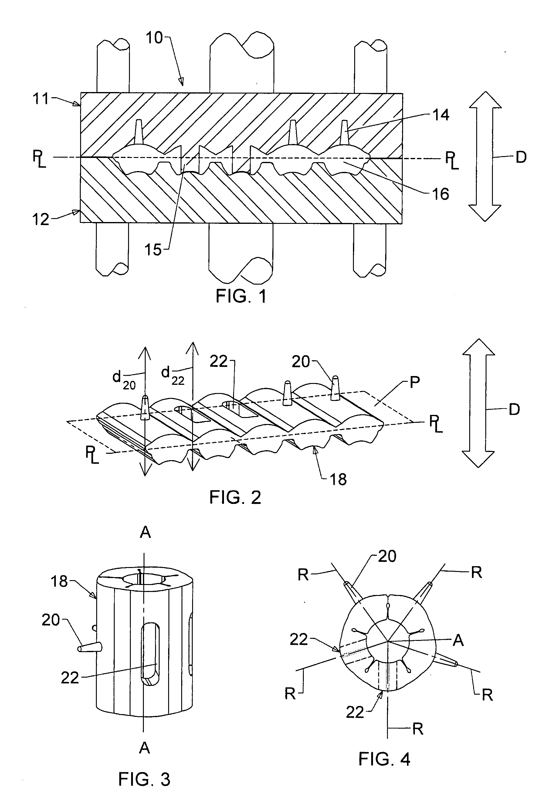
[0108]FIGS. 1-4 are schematic drawings illustrative of various terms and general relationships pertinent to the applicator and method of the present invention in certain embodiments thereof. In particular, FIG. 1 is a very simplified representation of pertinent features of an injection mold 10 of a generally conventional type suitable for use to produce molded plastic articles such as cosmetic applicators. The mold includes upper and lower mold plates 11 and 12 that are relatively movable toward and away from each other in a direction herein termed the “pull direction” and indicated by arrow D. The plates respectively have mold surfaces that face each other on opposite sides of a mold plane P which is perpendicular to pull direction D, the surfaces being configured as indicated at 14 and 15 to form projections and openings in the molded article. When brought together, the mold surfaces cooperatively define a mold cavity 16 to be filled with plastic material to be molded.

[0109] The ...


PUM

PropertyMeasurementUnit
angleaaaaaaaaaa
angleaaaaaaaaaa
flexibleaaaaaaaaaa

Abstract

A molded plastic applicator for cosmetics, such as a mascara brush, including an integral molded plastic panel that lies substantially in a mold plane when formed and is bent out of the mold plane to surround an extended longitudinal axis when the applicator is assembled. A plurality of openings, or projections such as bristles, are formed in or on the panel so as to be oriented substantially in a common pull direction transverse to the mold plane when the panel lies in the mold plane and to be oriented substantially radially of the longitudinal axis in directions distributed around the axis when the panel is bent to surround the axis. A retainer holds the panel bent out of the plane in surrounding relation to the axis. The panel may be formed as a plurality of free-ended limbs, radiating from a hub through which the longitudinal axis extends, and bent down around the axis; alternatively, it may be generally rectangular as formed, and bent into a cylinder about the axis, or it may be formed as a band that is wound helically about the axis. A method of making the applicator includes steps of molding the panel, bending the panel about the axis, and retaining the panel in the bent configuration.

Description

CROSS REFERENCE TO RELATED APPLICATIONS [0001] This application claims the benefit, under 35 U.S.C. §119(e), of U.S. provisional patent applications No. 60 / 838,973, filed Aug. 16, 2006, and No. 60 / 853,378, filed Oct. 20, 2006, the entire disclosures of both of which are incorporated herein by this reference.BACKGROUND OF THE INVENTION [0002] This invention relates to applicators for cosmetics, such as molded plastic applicators, and to methods of making them. In one important sense, to which detailed reference will be made herein for purposes of illustration but without limitation, the invention is particularly directed to brushes for applying mascara or the like. [0003] Brushes of the type commonly referred to as “twisted-in-wire” brushes, constituted of fibers clamped at their midpoints in a twisted wire core, are well known and widely used in the cosmetics industry. Although acceptable for uses exemplified by the application of mascara, these brushes have certain disadvantages. T...

Claims


Application Information

Patent Timeline
Patent Type & Authority Applications(United States)
IPC IPC(8): A45D40/26A46B3/18A46D1/00B29C33/42B29C53/02
CPCA45D40/267A46B9/021A46B2200/1053A46B2200/106B29L2031/42B29C45/0055B29C45/0081B29C2045/0056A46D1/00A45D40/265B29C53/02B29D21/00B29L2021/00
Inventor MALVAR, MICHAELJONAS, THOMAS
Owner ALBEA SERVICES SAS
Why Eureka
Try Eureka