Image display apparatus

a display apparatus and flat-type technology, applied in the direction of discharge tubes/lamp details, discharge tubes/lamp details, cathode ray tubes/electron beam tubes, etc., can solve the problems of insufficient reduction capability of color unevenness and generation of color unevenness, so as to prevent halation and reduce color unevenness

Inactive Publication Date: 2008-04-10
CANON KK
View PDF9 Cites 7 Cited by
  • Summary
  • Abstract
  • Description
  • Claims
  • Application Information

AI Technical Summary

Benefits of technology

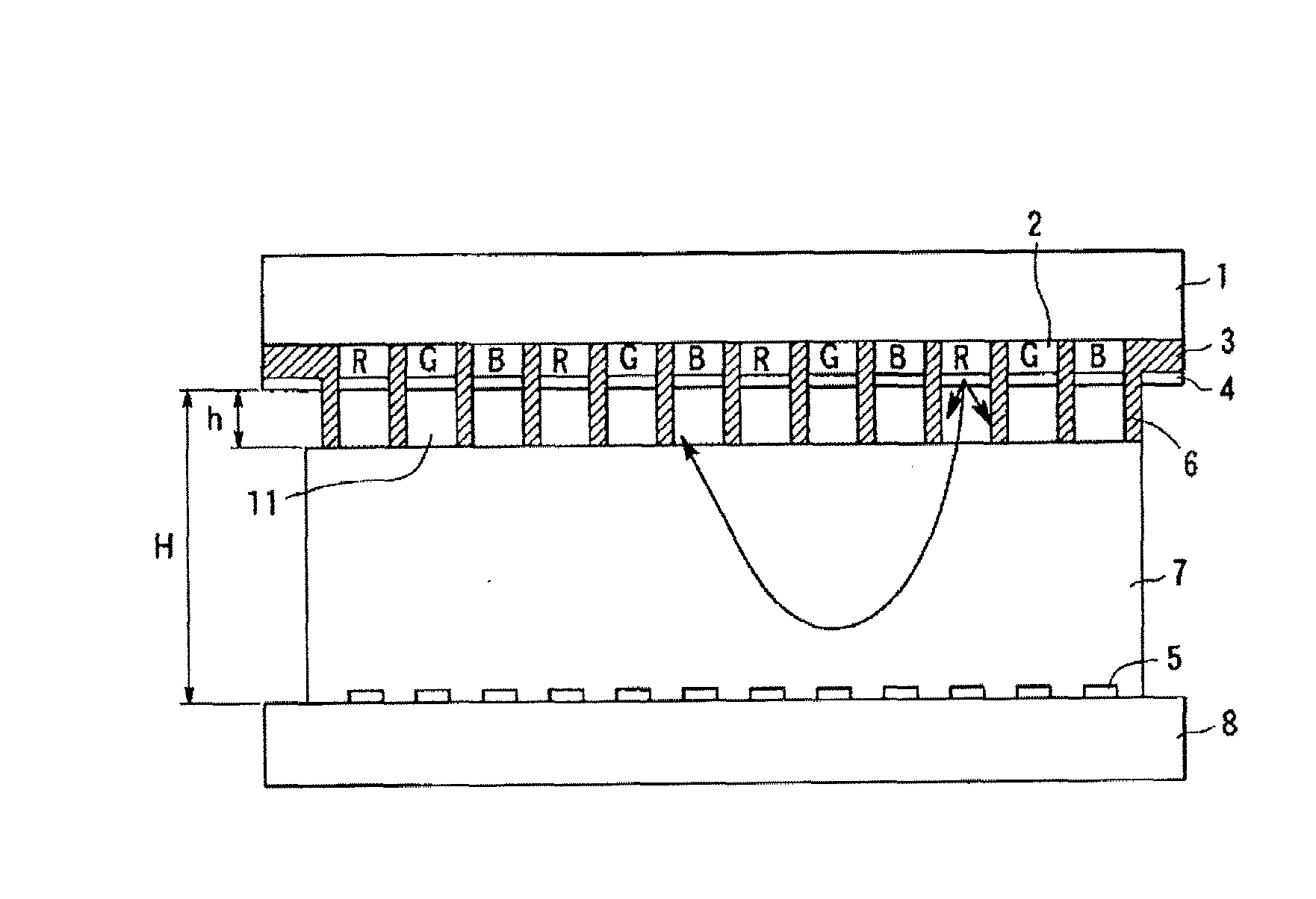
[0008]Therefore, an object of the present invention is to provide an image display apparatus that can prevent halation due to a reflection electron and decrease color unevenness to be generated caused by the halation.

Problems solved by technology

Because of halation due to a reflection electron, color unevenness is generated in the vicinity of a spacer.
According to a conventional structure, a reduction capability of color unevenness is not enough.

Method used


Image

  • Image display apparatus
  • Image display apparatus
  • Image display apparatus

Examples


embodiments

[0090]Hereinafter, the present invention will be described in detail with a specific embodiment(s).

first embodiment

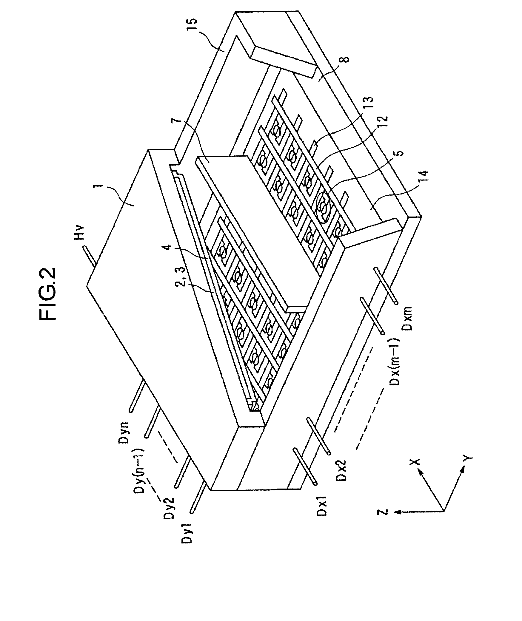
[0091]With reference to FIG. 14, FIG. 18A, and FIG. 12, a first embodiment of the present invention will be described. Further, in FIG. 18, a left side of the drawing is a cross sectional pattern diagram and a right side thereof is a plain pattern diagram.

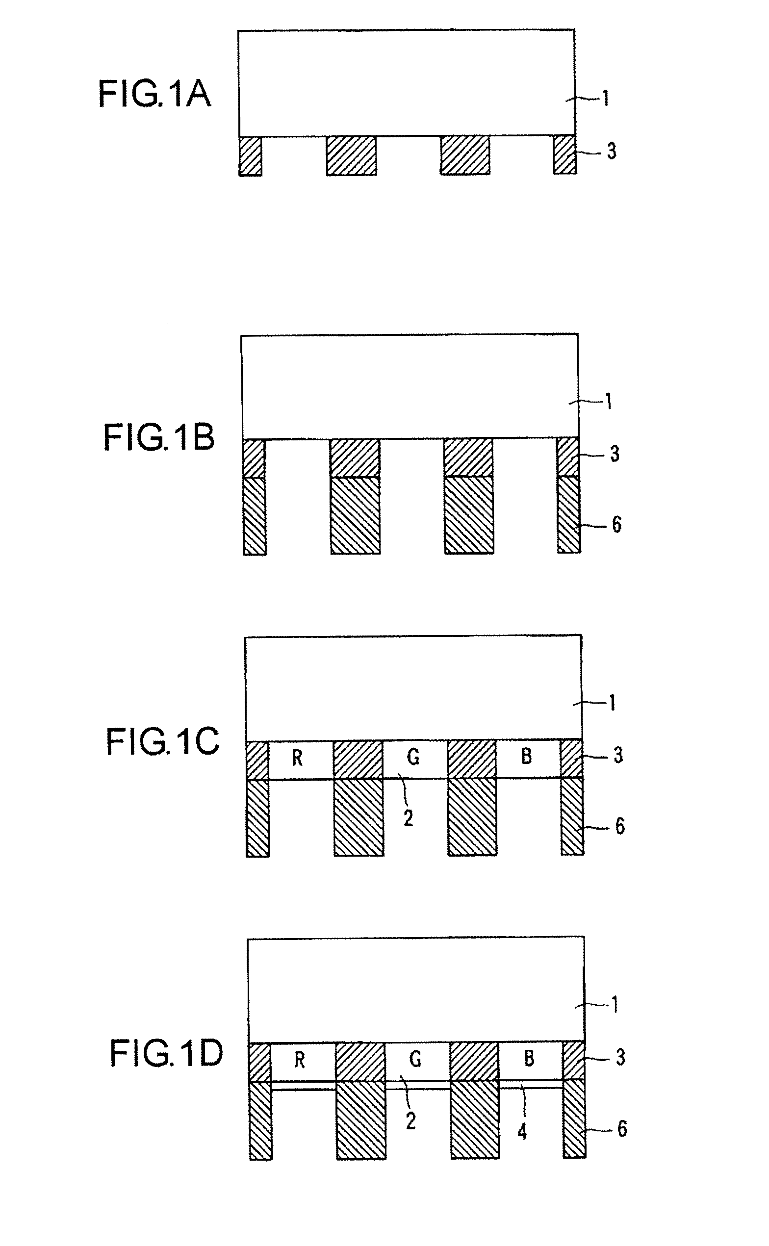
[0092]As shown in FIG. 14 and FIG. 18A, the face plate 1 used for the image display apparatus of the present embodiment has the fluorescence substances 2 of three colors (red, green, and blue). The black stripe 3 is formed between the fluorescence substances so as to divide respective fluorescence substances. The fluorescence substances for all colors are shaped in such a manner that their widths are defined to be 150 μm, their lengths are defined to be 600 μm, and their thicknesses are defined to be 15 μm. The black stripe 3 is shaped in such a manner that its width is 50 μm, its length is 600 μm, and its thickness is 15 μm. A square pixel of 600 μm×600 μm is formed by the fluorescent substances 2 of three colors and the black str...

second embodiment

[0103]Next, a second embodiment of the present invention will be described with reference to FIG. 18B. According to the present embodiment, a black matrix 16 in a grid is used in place of the black stripe 3. Other points are almost the same as the first embodiment, so that explanation thereof will not be described herein.

[0104]The black matrix 16 is used in order to improve a contrast of a bright place. The fluorescence substance has a high diffusion reflection rate, so that a whitish image is obtained on the bright place unless an average diffuse reflection rate is lowered by making the aperture ratio smaller.

[0105]Next, the measurement of the black matrix 16 will be described. Defining the width in the longitudinal direction of the black matrix 16 as 300 μm and the width in the lateral direction thereof as 50 μm, the aperture for one color is defined to be 150 μm×300 μm. The thickness thereof is defined to be 15 μm as same as the first embodiment. Moreover, the rib 6 in a stripe w...


PUM


Abstract

There is provided an image display apparatus comprising: a rear plate having a plurality of electron-emitting devices; a face plate having a plurality of fluorescence substances with different light emitting colors; and a plate-like spacer for defining an interval between the rear plate and the face plate, wherein the spacer has an aperture that allows a reflection electron generated on the face plate to pass through the plate-like spacer in a thickness direction and to reenter the face plate, and wherein the amount Et of the reflection electron that is irradiated to the fluorescence substance closest to the spacer through the aperture is defined as Et>0.3×En, where the amount of the reflection electron to be irradiated to the fluorescence substance is En when no spacer is located.

Description

BACKGROUND OF THE INVENTION[0001]1. Field of the Invention[0002]The present invention relates to a flat-type image display apparatus that is configured by using an electron-emitting device.[0003]2. Description of the Related Art[0004]In Japanese Patent Application Laid-Open No. 7-45221, as a structure for preventing damage of a metal back and making positioning simple upon connection between a face plate and a spacer, a structure such that the face plate is provided with a rib is disclosed.[0005]In U.S. Pat. No. 5,576,596, as a structure for decreasing mixture of colors and reducing a damage of a member of the face plate, a structure of the face plate provided with a rib is described.[0006]In a specification of Japanese Patent No. 3270054, there is described a structure such that a rib as a shielding structure is disposed on a face plate in an electric field emitting apparatus having an inner structure for aligning a fluorescence pixel in a corresponding electric field emitter in or...

Claims


Application Information

Patent Timeline
Patent Type & Authority Applications(United States)
IPC IPC(8): H01J1/62
CPCH01J29/864H01J2329/863H01J2329/8625H01J31/127
Inventor HAYAMA, AKIRA
Owner CANON KK
Why Eureka
Try Eureka