
Headlight Control Apparatus for Automobile

Inactive Publication Date: 2008-04-10
HITACHI LTD
View PDF13 Cites 46 Cited by
  • Summary
  • Abstract
  • Description
  • Claims
  • Application Information

AI Technical Summary

Benefits of technology

[0008] Accordingly, the present invention provides a headlight control apparatus which suppresses a feeling of strangeness given to a driver of an own vehicle by hunting due to reflector light while preventing a preceding vehicle and an on-coming vehicle from being dazzled, on the basis of a video image obtained by a camera.
[0010] More preferably, there is provided a headlight control apparatus including a headlight for irradiating a front region of a vehicle, of which light quantity can be controlled in every partial area in the irradiated region, a camera mounted on the vehicle for capturing an image of the front region of the vehicle, and a control unit for detecting a position of a light spot in the image inputted from the camera to control an irradiation pattern of the headlight based on the position of the light spot, wherein the control unit is configured to control the headlight so as to reduce the light quantity in a certain area above the portion of the detected light spot.
[0011] According to the invention, even if the reflector light causes the hunting, the irradiation light quantity of the entire irradiated area does not vary, but only the irradiation light quantity in a partial area above the reflector varies, and therefore, the feeling of strangeness given to the driver can be suppressed.

Problems solved by technology

However, since the reflection light from the reflector becomes weak at the moment of switching the headlight to the low beam, it is determined that the headlight beam becomes absent, and the operation of switching the headlight to the high beam is repeated.
There is the possibility that this hunting causes a feeling of strangeness of the driver of the own vehicle.

Method used


Image

  • Headlight Control Apparatus for Automobile
  • Headlight Control Apparatus for Automobile
  • Headlight Control Apparatus for Automobile

Examples


Embodiment Construction

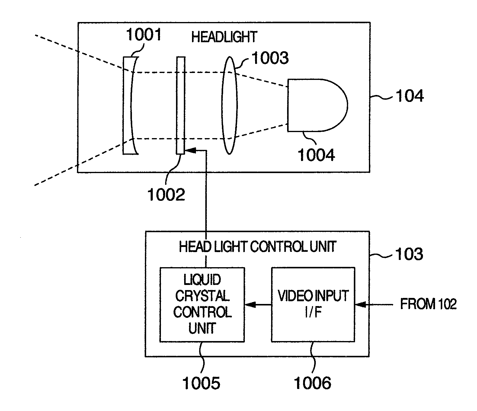
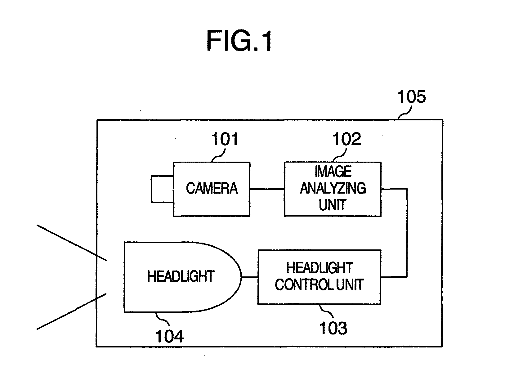
[0024]FIG. 1 is a schematic diagram showing an entire configuration for achieving a method of controlling light distribution of a headlight, which is an embodiment according to the present invention. A cameral 101 is mounted on a vehicle so as to capture a field of view ahead of the vehicle, and a headlight 104 is mounted on the vehicle so as to illuminate a front region ahead of the vehicle.

[0025] Regarding the arrangement, it is desirable that the camera 101 and the headlight 104 are installed as near to each other as possible. This leads to simplification of calibration of optical axis adjustment or the like. As shown in FIG. 1, it is convenient from the viewpoint of the optical axis adjustment to install both the camera 101 and the headlight 104 inside one headlight unit 105. This is because the optical axis of the camera 101 and the optical axis of the headlight 104 can be aligned with each other within the range of a certain assembly tolerance, and therefore, by adjusting the...


PUM


Abstract

The present invention provides a headlight control apparatus which suppresses a feeling of strangeness given to a driver of an own vehicle by hunting due to reflector light while preventing a preceding vehicle and an on-coming vehicle from being dazzled, based on a video image obtained by a camera. The headlight is controlled by detecting the position of a light spot in the image captured by the camera to perform irradiation with a pattern which reduces the light quantity of a certain area above the detected light spot. Thereby, even if hunting occurs due to the reflector light, the irradiation light quantity of an entire irradiation area of the headlight does not vary, but only the irradiation light quantity for a partial area above a reflector varies, and therefore, the feeling of strangeness given to the driver can be suppressed.

Description

BACKGROUND OF THE INVENTION [0001] 1. Field of the Invention [0002] The present invention relates to a headlight control apparatus for an automobile. [0003] 2. Description of Related Art [0004] There has been researched and developed an art of automatically switching a high beam and a low beam of a headlight by analyzing a video image of an on-vehicle camera. [0005] JP-B-6-55581 discloses an art of switching a headlight from a high beam to a low beam so as not to cause a driver of a preceding vehicle or an on-coming vehicle to be dazzled, by detecting tail light of the preceding vehicle or a headlight of the on-coming vehicle in a video image of a color camera. [0006] JP-A-2002-526317 discloses a technique of continuously controlling an irradiation area of a headlight by calculating a distance to a preceding vehicle or an on-coming vehicle on the basis of a state of a headlight and a tail lamp in an image of a camera to further improve the above art. According to this technique, it ...

Claims


Application Information

Patent Timeline
IPC IPC(8): B60Q1/14
CPCB60Q1/0023B60Q1/1423B60Q2300/056H04N7/183B60Q2300/42F21S48/1731B60Q2300/41F21S41/645
Inventor OTSUKA, YUJIMURAMATSU, SHOJISHIMA, TAKESHIMONJI, TATSUHIKO
Owner HITACHI LTD
Learn More