
Control system for four-wheel drive vehicle

a control system and four-wheel drive technology, applied in the field of four-wheel drive vehicles, can solve the problems of large change in driving force driver experience etc., and achieve the effect of suppressing a feeling of strangeness

Active Publication Date: 2016-03-01
TOYOTA JIDOSHA KK
View PDF3 Cites 2 Cited by
  • Summary
  • Abstract
  • Description
  • Claims
  • Application Information

AI Technical Summary

Benefits of technology

The patent is about a control system for a four-wheel drive vehicle that includes an automatic transmission and a disconnect mechanism. The system is designed to make the driver feel less strangeness when the disconnect mechanism is engaged or released. Electronic control unit may start the engagement or release of the disconnect mechanism without waiting for a command to shift the automatic transmission when a predetermined condition is satisfied, such as a slip. The technical effect of this invention is to improve the driver's experience and comfort while engaging or releasing the disconnect mechanism.

Problems solved by technology

When the disconnect mechanism is engaged or released at arbitrary timing not intended by a driver, the driver experiences a feeling of strangeness because of, for example, a change in rotational inertia while the disconnect mechanism is being engaged or released.
As a result, a driver experiences a feeling of strangeness.
Particularly, when the automatic transmission is controlled to neutral, a change in driving force is large.
Thus, a feeling of strangeness experienced by the driver also increases.
When the automatic transmission is changed to high gear as well, the automatic transmission needs to be changed to an ordinary speed stage after a change of the disconnect mechanism, so the automatic transmission is further shifted, with the result that the driver experiences a feeling of strangeness.

Method used


Image

  • Control system for four-wheel drive vehicle
  • Control system for four-wheel drive vehicle
  • Control system for four-wheel drive vehicle

Examples


first embodiment

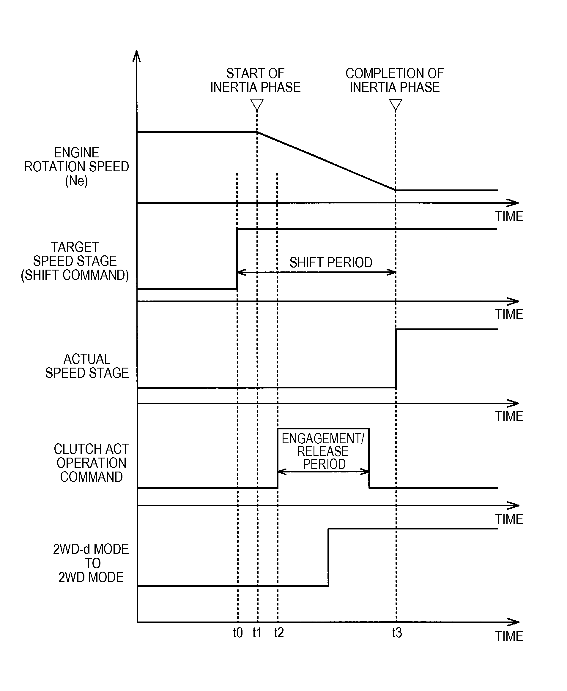
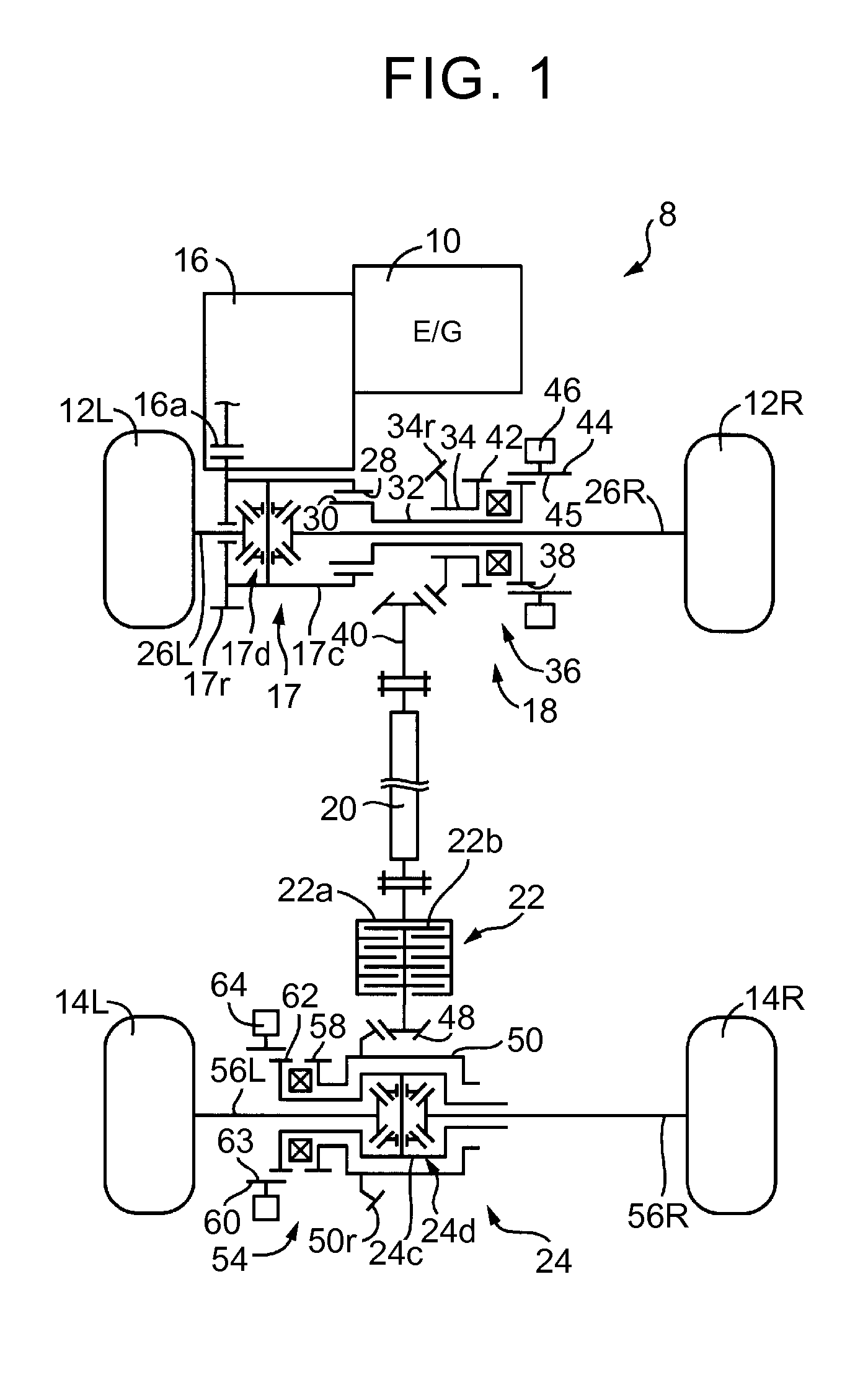
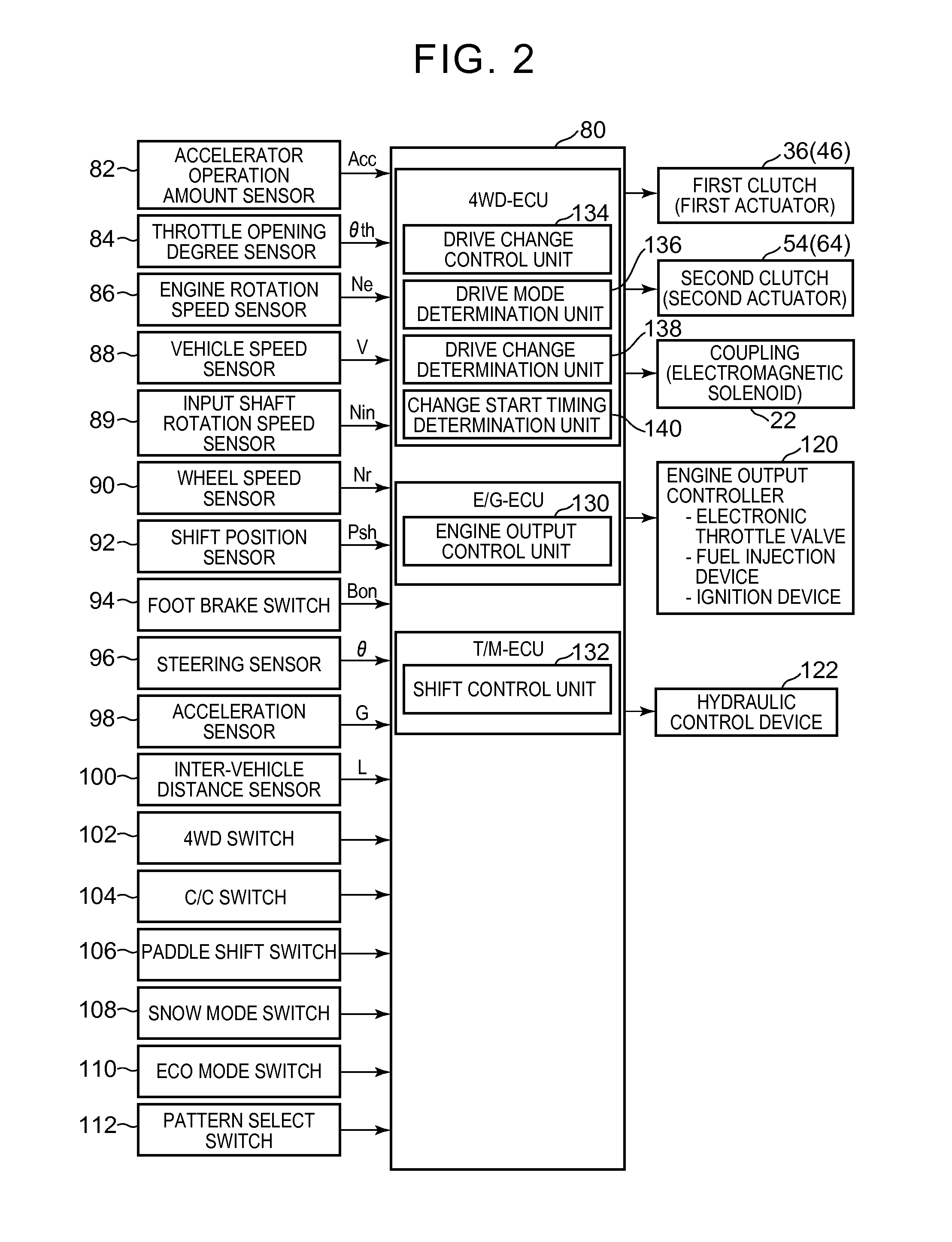
[0032]the invention will be described. FIG. 1 is a skeletal view that schematically illustrates the configuration of a four-wheel drive vehicle 8 that is an embodiment of the invention. As shown in FIG. 1, the four-wheel drive vehicle 8 includes a four-wheel drive system based on an FF system. The four-wheel drive vehicle 8 includes an engine 10 as a driving source, and includes a first power transmission path and a second power transmission path. The first power transmission path transmits power of the engine 10 to front wheels 12R, 12L (when not particularly distinguished from each other, referred to as front wheels 12). The second power transmission path transmits power of the engine 10 to rear wheels 14R, 14L (when not particularly distinguished from each other, referred to as rear wheels 14). The four-wheel drive vehicle 8 includes an automatic transmission 16, a front differential 17, a transfer 18, a propeller shaft 20, a coupling 22, a rear differential 24, and the like. Alt...

second embodiment

[0111]the invention will be described. In the above-described embodiment, until the inertia phase of the automatic transmission 16 is started, engagement or release (change) of the clutches 36, 54 are delayed. In the present embodiment, a shift of the automatic transmission 16 is started during engagement or release of the clutches 36, 54. That is, output of a command to shift the automatic transmission 16 is delayed. FIG. 5 is a functional block diagram that illustrates a relevant portion of control functions of an electronic control unit 150 according to the present embodiment. The electronic control unit 150 shown in FIG. 5 differs from the electronic control unit 80 according to the above-described embodiment in that the change start timing determination unit 140 of the 4WD-ECU is omitted and a shift start timing determination unit 152 is added to the T / M-ECU. Hereinafter, the newly added shift start timing determination unit 152 will be mainly described, and the description of ...

third embodiment

[0120]the invention will be described. In the present embodiment, when it is determined to change the drive mode on the basis of an operation of the 4WD switch 102 and it is determined to shift the automatic transmission 16 on the basis of an automatic shift condition that is prescribed based on a vehicle traveling state thereafter, at least one of the automatic transmission 16 or the pair of clutches 36, 54 is controlled such that the engagement-release period of the clutches 36, 54 and the shift period of the automatic transmission 16 at least partially overlap with each other.

[0121]FIG. 7 is a functional block diagram that illustrates a control system of an electronic control unit 180 corresponding to further another embodiment of the invention and a relevant portion of control functions associated with a change of the front / rear wheel driving state. The electronic control unit 180 shown in FIG. 7 differs from the electronic control unit 80 according to the above-described embodi...


PUM


Abstract

A disconnect mechanism is configured to disconnect a predetermined rotating element from an engine and an auxiliary drive wheels while the vehicle is traveling in a two-wheel drive mode. The predetermined rotating element is configured to transmit power to the auxiliary drive wheels while the vehicle is traveling in a four-wheel drive mode. An electronic control unit is configured to: execute shift control when a shift condition of an automatic transmission is satisfied; selectively engage or release the disconnect mechanism based on a traveling state of the vehicle and a driver's predetermined operation; and control at least one of the automatic transmission or the disconnect mechanism such that a shift period based on the shift condition of the automatic transmission and an engagement-release period of the disconnect mechanism at least partially overlap with each other.

Description

INCORPORATION BY REFERENCE[0001]The disclosure of Japanese Patent Application No. 2013-239372 filed on Nov. 19, 2013 including the specification, drawings and abstract is incorporated herein by reference in its entirety.BACKGROUND OF THE INVENTION[0002]1. Field of the Invention[0003]The invention relates to a four-wheel drive vehicle and, more particularly, to a control system for a four-wheel drive vehicle including an automatic transmission and a disconnect mechanism, the automatic transmission being provided in a power transmission path between an engine and both main drive wheels and auxiliary drive wheels, the disconnect mechanism being provided in a power transmission path between the automatic transmission and the auxiliary drive wheels and configured to selectively connect or interrupt the power transmission path.[0004]2. Description of Related Art[0005]There has been suggested a four-wheel drive vehicle including an engine, main drive wheels, auxiliary drive wheels, an auto...

Claims


Application Information

Patent Timeline
Patent Type & Authority Patents(United States)
IPC IPC(8): B60W10/119B60W10/10
CPCB60W10/119B60W10/10B60W10/11B60W30/19
Inventor TAMOTO, HIDEKIARAI, MASAYUKIOBAYASHI, YOSHIROIWATSUKI, KUNIHIRO
Owner TOYOTA JIDOSHA KK
Learn More