
Self-aligning terminal block for battery pack

Active Publication Date: 2008-04-10
SNAP ON INC
View PDF23 Cites 17 Cited by
  • Summary
  • Abstract
  • Description
  • Claims
  • Application Information

AI Technical Summary

Benefits of technology

[0009]The present construction is in contrast to the prior art that used tight or intolerant component assemblies to connect the terminals to the batteries. These prior art devices sometimes fail due to misalignment or vibration. The floating design helps to guarantee consistent electrical connections regardless of variations in the alignment of the tool terminals and the battery terminals or vibration from operating the tool. Also, the design should result in less breakage of terminal components.
[0010]The disclosure includes a hand-held power tool having a rechargeable battery in a removable battery pack that connects (i.e. slides) onto a tool body to electrically connect to a tool terminal assembly in the tool body. The tool includes a self-aligning terminal block having electrical contacts in the tool terminal assembly, wherein electrical contacts of the terminal block are female terminals with resilient guideways that taper away from each other at distal ends, preferably forming an enlarged entry area to help receive and align the battery terminal blades as the blades are inserted into narrow sections of the female terminals, so that the guideways can be aligned with battery terminal blades functioning as electrical contacts of the battery pack. The self-aligning terminal block has clearance on at least one side, preferably two or four, to allow lateral movement within the tool body to keep constant contact with mating electrical contacts of the terminal block and the battery pack.

Problems solved by technology

These prior art devices sometimes fail due to misalignment or vibration.

Method used


Image

  • Self-aligning terminal block for battery pack
  • Self-aligning terminal block for battery pack
  • Self-aligning terminal block for battery pack

Examples


Embodiment Construction

[0017]While the present disclosure may be susceptible to embodiment in different forms, there is shown in the drawings, and herein will be described in detail, embodiments with the understanding that the present description is to be considered an exemplification of the principles of the disclosure and is not intended to be exhaustive or to limit the disclosure to the details of construction and the arrangements of components set forth in the following description or illustrated in the drawings.

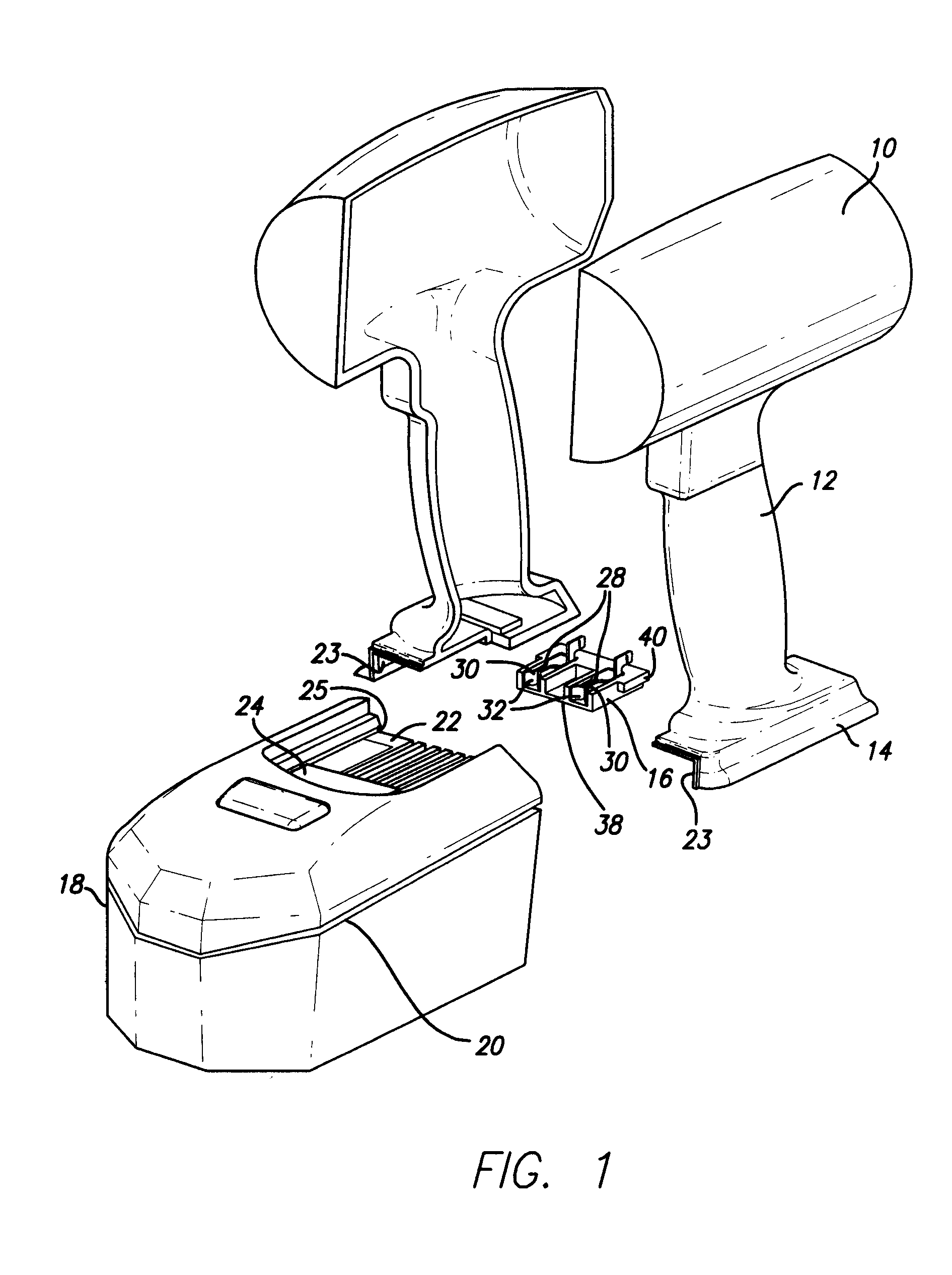
[0018]FIG. 1 shows an exploded cordless hand-held power tool 10 having a tool body 12 including a pedestal base 14, a tool terminal assembly 16 and a battery pack 18 including a recharageable battery 20 (not shown inside battery pack) and a shoe 22 for slideably receiving the pedestal base 14. A typical tool would also have a drive motor and other components to accomplish the specific operation of the tool. The battery pack 18 is removable and slides into a tool body 12 to electrically connect...


PUM


Abstract

A self-aligning terminal block in a tool terminal assembly having electrical contacts for connecting to a removable battery pack to be used in conjunction with hand-held power tools having a rechargeable battery. The electrical contacts of the terminal block are preferably female terminals with two resilient guideways that taper away from each other at distal ends, preferably forming an enlarged entry area to help receive and align the battery terminals as they are inserted into narrow sections of the female terminals. The guideways can be aligned with battery terminal blades functioning as electrical contacts of the battery pack. The self-aligning terminal block has clearance on at least one side to allow lateral movement within the tool body to keep constant contact with mating electrical contacts of the terminal block and the battery pack.

Description

FIELD OF INVENTION[0001]This invention relates to portable cordless power tools with removable batteries, and specifically to a self-aligning terminal block for use with a battery pack that provides electricity to such tools.BACKGROUND[0002]Certain power tools are made to be portable with removable batteries to allow for recharging. A battery pack is attached to the power tool to provide power for operation of the tool. Power tools are known having shoe batteries with horizontal slide-in locking features.[0003]The prior art includes hand-held power tools with releasably mountable battery units for providing electrical current. The battery unit can have contact surfaces that align with contacts connected to the motor. Electrical coupling of drive motors with removable battery units can be made by pedestal connections and horizontal slide-in shoe connections.[0004]One of the problems that occurs with power tools having removable battery packs is that the tool terminals may not properl...

Claims


Application Information

Patent Timeline
IPC IPC(8): H02J7/00H01M50/202H01M50/244H01M50/247H01M50/296
CPCH01M2/1022H01R31/06H01R13/6315Y02E60/10H01M50/247H01M50/202H01M50/296H01M50/244
Inventor GRIFFIN, PAUL W.
Owner SNAP ON INC
Features
  • Generate Ideas
  • Intellectual Property
  • Life Sciences
  • Materials
  • Tech Scout
  • Unparalleled Data Quality
  • Higher Quality Content
  • 60% Fewer Hallucinations
Learn More