Direct-current permanent magnet motor iron core

A permanent magnet motor and iron core technology, applied in the field of motor iron core, can solve problems such as inconvenience and achieve the effect of reducing resistance

Pending Publication Date: 2022-01-18
张煜
View PDF0 Cites 0 Cited by
  • Summary
  • Abstract
  • Description
  • Claims
  • Application Information

AI Technical Summary

Problems solved by technology

Nowadays, when the maintenance personnel are repairing the motor, most of them wind the iron core coil by hand, so it is very inconvenient

Method used


Image

  • Direct-current permanent magnet motor iron core
  • Direct-current permanent magnet motor iron core
  • Direct-current permanent magnet motor iron core

Examples


Embodiment approach

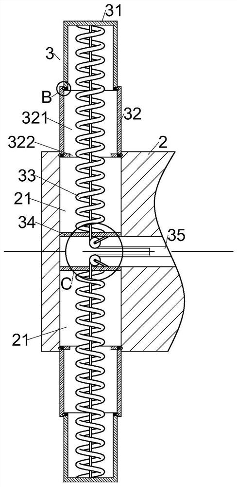
[0032] As a specific embodiment of the present invention, the inner wall of the bottom end of No. 1 telescopic rod 31 and No. 2 telescopic rod 32 is provided with No. 2 groove 323, and the No. 2 groove 323 of No. 1 telescopic rod 31 and No. 2 telescopic rod 32 All be provided with clamping ball 311 and clamping spring 312 in the groove 323, clamping ball 311 is positioned at the outside of No. One end away from the stuck ball 311 is all fixedly connected with the side inner wall of the No. 1 telescopic rod 31 and the No. 2 telescopic rod 32 and the second groove 323, and the inner surface of the No. 2 telescopic rod 32 and the winding plate 2 are all provided with the inner surface of the stuck ball. 311 is matched with the card slot 313.

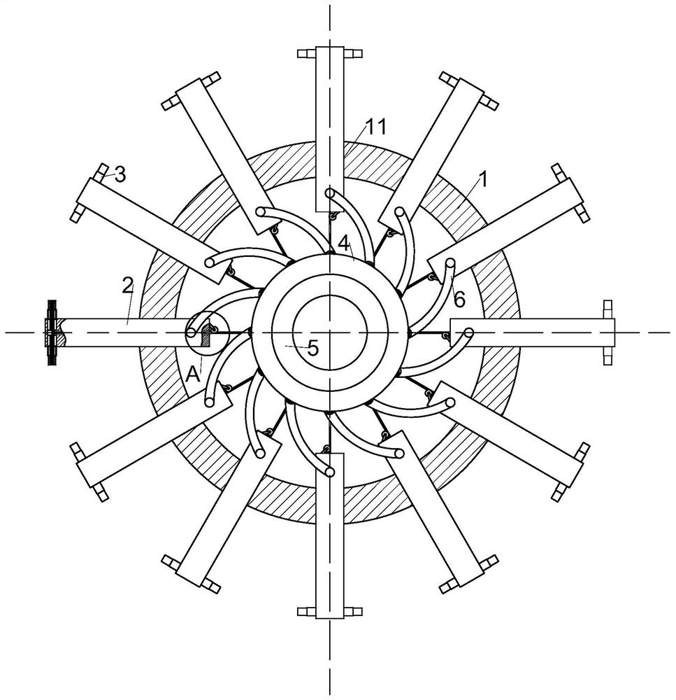
[0033] When the sleeve 4 rotates counterclockwise, it drives the steel wire rope 35 to move to move the limit rod 3 to the direction of the winding plate 2. When the sleeve 4 rotates, the limit rod 3 makes the No. No. 32 telescopic rods 32...


PUM


Abstract

The invention relates to the field of motor iron cores, and concretely relates to a direct-current permanent magnet motor iron core. The direct-current permanent magnet motor iron core comprises an iron ring, a wire winding plate, a limiting rod, a sleeve, a bearing, a connecting rod and a fixing frame, first through holes which are evenly distributed are formed in the outer surface of the iron ring, the wire winding plate is slidably connected into the first through holes in the iron ring, a T-shaped through hole is formed in the wire winding plate, the end, located on the outer surface of the iron ring, of the winding plate is rotationally connected with the limiting rod, the bottom end of the limiting rod is located in the T-shaped through hole, the sleeve is arranged in the iron ring and rotationally connected with a motor rotating shaft through the bearing, the connecting rod is hinged to the outer surface of the sleeve, the other end of the connecting rod is hinged to the outer surface of the winding plate, the outer surfaces of the two ends of the iron ring are fixedly connected with the fixing frame, and the fixing frame is fixedly connected with the motor rotating shaft. Movement of the winding rod and the fixing rod is achieved by rotating the sleeve, so the purpose that maintenance personnel can conveniently wind coils with hands is achieved.

Description

technical field [0001] The invention relates to the field of motor iron cores, in particular to a DC permanent magnet motor iron core. Background technique [0002] The fixed part of the motor is called the stator, on which a pair of stationary main magnetic poles of DC excitation are installed; the rotating part is called the armature core, on which the armature winding is installed, and the induced electromotive force is generated after power-on, acting as Rotating magnetic field; after that, electromagnetic torque is generated for energy conversion. According to the shape of the stator winding and the way of embedded installation, the stator winding can be divided into two types: centralized and distributed according to the shape of the coil winding and the way of embedded wiring. [0003] Due to the structure of the motor itself, the motor is easily damaged after working for a long time. When the winding of the motor is damaged, most motor users will choose to repair i...

Claims


Application Information

Patent Timeline
Patent Type & Authority Applications(China)
IPC IPC(8): H02K1/18H02K3/46H02K15/08
CPCH02K1/18H02K3/46H02K15/08
Inventor 张煜李岭松尹宇华
Owner 张煜
Why Eureka
Try Eureka